1. Out-of-position airbag safety
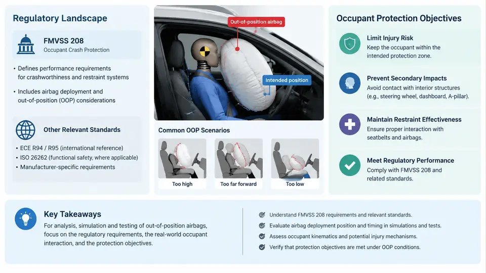
Airbags are supplemental restraint systems (SRS) engineered to deploy in tens of milliseconds during a moderate-to-severe frontal crash. Their protective benefit, however, depends on the occupant being seated in a nominal, upright posture at a defined distance from the instrument panel. When an occupant is out of position (OOP) — leaning forward, resting against the airbag module, sitting on the seat edge, or positioned near the side curtain — the deploying cushion can strike the head, neck, or chest at high velocity before the bag has fully inflated. This interaction can produce serious or fatal injuries, particularly to small-stature occupants and children. Out-of-position airbag safety is therefore the discipline of characterizing, simulating, and mitigating these non-nominal occupant–airbag interactions.
Why OOP Matters: The Injury Mechanism
An inflator fills the cushion in roughly 20–50 ms. During that window, the cushion surface moves outward at speeds that can exceed 200 m/s at the module vent. If the occupant's head or chest is within the deployment path, the cushion transfers momentum directly to the body region before the bag has softened through venting and membrane stretch. The resulting loading is highly localized and can generate head acceleration, neck shear, and chest deflection far above the thresholds associated with a nominal, in-position occupant. The core engineering problem is thus a timing and proximity problem: the closer the occupant is to the module, and the earlier in the deployment the contact occurs, the more severe the loading.
The Regulatory Landscape
In the United States, FMVSS 208 (Federal Motor Vehicle Safety Standard No. 208, "Occupant Crash Protection") is the central regulation governing frontal occupant protection, including airbag performance. It establishes requirements for both belted and unbelted occupants and, critically, defines test procedures that include out-of-position scenarios. Key elements relevant to OOP safety include:
- Static deployment tests using the "out-of-position" test matrix, which places anthropomorphic test devices (ATDs) such as the Hybrid III 3-year-old, 6-year-old, and small female (5th percentile) in specified positions relative to the airbag module.
- Suppression and low-risk deployment (LRD) requirements: airbags must either be suppressed when a child or small occupant is detected in a risky position, or deploy in a manner that limits injury risk.
- Occupant detection and classification via weight sensors, seat track position sensors, and belt tension/position sensors, which feed the restraint control module (RCM) to decide deployment level or suppression.
Internationally, UN Regulation No. 94 and the European New Car Assessment Programme (Euro NCAP) add OOP assessment protocols, while China's GB 11551 and C-NCAP incorporate similar static deployment checks. The trend across all regimes is toward performance-based criteria: rather than prescribing a specific inflator design, regulators specify injury metrics that must not be exceeded under defined OOP conditions.
Occupant Protection Objectives
The overarching objective is to ensure that airbag deployment does not itself become the primary injury source. This translates into several measurable targets:
| Objective | Typical Metric | Representative Threshold (example) |
|---|---|---|
| Limit head injury | HIC 15 (Head Injury Criterion) | ≤ 700 for OOP static deployment |
| Limit neck loading | Nij (Neck Injury Criterion) | ≤ 1.0 |
| Limit chest deflection | Peak chest compression | ≤ 50 mm (small female) |
| Prevent membrane contact | Time-to-contact vs. inflation | Contact after cushion softening |
These thresholds are illustrative and vary by regulation, ATD, and body region. The engineering intent is consistent: keep the deploying cushion from delivering concentrated energy to a vulnerable body region before the bag has reached a compliant state.
From Regulation to Simulation: The OOP Workflow
Meeting FMVSS 208 OOP requirements is not a single test but a workflow that couples occupant packaging, inflator characterization, and explicit dynamic simulation. A typical sequence is:
- Define the OOP test matrix — select ATD sizes, positions (e.g., head on module, chest on module, 6-year-old leaning forward), and deployment temperature extremes.
- Characterize the inflator — measure tank pressure vs. time and mass flow rate to build a gas-inflow model for simulation.
- Build the finite element model — mesh the cushion, module, and ATD; assign fabric properties, venting, and contact definitions.
- Run explicit dynamic simulation — solve the coupled fluid–structure interaction (FSI) or use a uniform-pressure inflator model with a control volume.
- Evaluate injury metrics — extract HIC, Nij, and chest deflection; compare against thresholds.
- Iterate on design — adjust inflator output, vent size, cushion fold pattern, or add active venting/tethers.
The simulation is only as good as its inflator model. A common failure mode is an over-simplified mass flow curve that inflates the cushion too quickly, producing artificially high contact forces. Conversely, an under-driven model may show no contact at all, masking a real risk. Calibration against tank tests and static deployment photography is essential.
Visualizing the OOP Interaction Chain
The diagram below maps the causal chain from occupant position through deployment to injury outcome, and shows where simulation and regulation intervene. It is not a process flowchart but a signal-and-loading relationship map: the occupant's proximity sets the initial condition, the inflator output drives the cushion kinematics, and the contact timing determines which injury metric dominates.
Key Takeaways for the Simulation Engineer
Regulatory compliance is the floor, not the ceiling. FMVSS 208 defines the OOP test matrix and injury thresholds, but real-world safety depends on robust design across the full occupant population. When building a simulation model, the most influential parameters are the inflator mass flow curve, the initial occupant offset, and the cushion vent area. A sensitivity study on these three variables typically reveals that a 20% reduction in early mass flow can lower peak head acceleration by 30–40% in a head-on-module scenario, while an increase in vent area primarily affects the late-stage cushion pressure and chest loading. These relationships should be quantified early, because they determine whether a design can pass OOP requirements without resorting to suppression — which itself carries risk if the occupant detection system misclassifies a small adult as a child.
The next step in any OOP program is to translate these regulatory and physical relationships into a concrete simulation setup: defining the ATD positioning, calibrating the inflator model, and selecting the contact algorithm. That is where the engineering work becomes measurable.