3. Overview of seatbelt modeling approaches
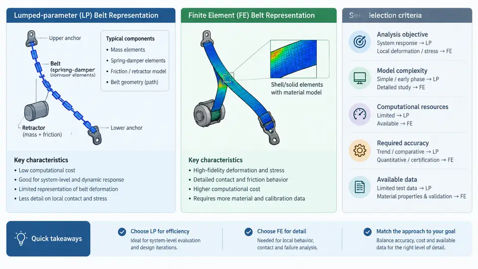
Seatbelt modeling in PAM-CRASH is not a single technique but a spectrum of representations, each trading geometric fidelity against computational cost. The two endpoints of that spectrum are the lumped-parameter (LP) belt and the finite element (FE) belt. Between them sit hybrid strategies that combine LP retractor and slipring behavior with FE webbing in regions where contact and folding matter. Choosing the right representation is one of the earliest and most consequential decisions in an occupant protection model, because it determines which physical phenomena the simulation can capture at all.
What each representation actually models
A lumped-parameter belt is a chain of discrete elements: a retractor with a locking mechanism, a slipring (D-ring) that redirects the belt path, one or more segments representing the webbing between anchor points, and a buckle/latch connection. Each segment carries a force–elongation characteristic rather than a discretized geometry. The belt path is defined by node positions and the routing through sliprings, and the webbing itself has no bending stiffness, no shell elements, and no through-thickness behavior. Load transfer is governed by the segment's stiffness curve, which is typically derived from a tensile test of the actual webbing.
An FE belt discretizes the webbing with membrane or shell elements — in PAM-CRASH typically membrane elements with no bending resistance, since real webbing buckles readily. Each element follows the material law assigned to it, and the belt can fold, twist, and drape over the occupant and seat. Contact between the belt and the occupant is resolved element by element, so pressure distribution across the chest and pelvis emerges from the simulation rather than being assumed.
The practical difference is stark. An LP belt can be built and tuned in hours and runs in minutes. An FE belt may take days to mesh, route, and stabilize, and can dominate the runtime of the entire occupant model. The question is never "which is better" in the abstract, but "which phenomena does my load case require."
Selection criteria
The decision hinges on four questions, applied in order:
- Does the load case require belt–occupant contact pressure distribution? If you are assessing chest deflection, rib fracture risk, or submarining, the belt must be able to conform to the body. That requires FE webbing over the torso and pelvis.
- Does the belt geometry change significantly during the event? Pretensioner pull-in, belt spooling, and the belt sliding across the shoulder all change the path. LP belts handle path changes through slipring routing and segment length changes; FE belts handle them through actual node motion.
- Is the belt folding or bunching? Webbing that gathers at the buckle or folds over the iliac crest cannot be represented by a single force–elongation curve. FE is mandatory here.
- What is the runtime budget? If the model must run hundreds of design-of-experiments iterations, an LP belt may be the only feasible choice, accepting reduced fidelity.
Hybrid modeling: the practical middle ground
Most production PAM-CRASH occupant models are hybrids. The retractor, slipring, and buckle are LP elements because their internal mechanics — spool rotation, locking pawl engagement, latch release — are not the subject of the simulation. The webbing over the chest and pelvis is FE because that is where contact and injury metrics live. The transition between LP and FE domains is handled by a shared node or a tied interface, and the belt tension is continuous across it.
This hybrid approach is not a compromise so much as a targeted allocation of fidelity. The LP retractor provides a force–time or force–displacement output that drives the FE webbing, and the FE webbing provides the contact pressure that the LP retractor cannot. The interface must be checked carefully: a mismatch in belt tension across the LP–FE boundary produces non-physical slack or over-tension that corrupts the entire occupant response.
Building an LP belt: what the inputs look like
An LP belt in PAM-CRASH is defined through a small set of cards. The retractor is typically a type 7 or type 8 seatbelt element with a locking time and a force-limiting characteristic. The webbing segments are type 4 or type 5 elements with a load–elongation curve. A representative webbing curve for a 48 mm polyester belt might be:
WEBBING_LOAD_CURVE (example, not measured)
  elongation [%]    force [kN]
  0.0               0.0
  1.0               2.5
  2.0               5.0
  4.0               8.5
  6.0               11.0
  8.0               12.5
  10.0              13.0
These values are illustrative. In practice the curve comes from a tensile test at the relevant strain rate, because webbing is rate-sensitive. The retractor locking time is set to match the pretensioner firing signal, and the load limiter is a force cap that the retractor card applies once the belt force exceeds a threshold — typically 3 to 5 kN for a modern load-limited system.
The slipring is a node with a friction coefficient. If the belt slides freely, friction is near zero; if the D-ring has a coating that resists sliding, a small friction coefficient (0.05–0.15) is applied. This matters because it determines how much of the retractor force reaches the shoulder versus the lap portion.
Building an FE belt: the critical steps
An FE belt requires a mesh, a material, and a routing. The mesh is a strip of membrane elements, typically 10–15 mm wide and 10–20 mm long, following the belt centerline. The material is a fabric law — in PAM-CRASH, a membrane material with a nonlinear stress–strain curve and no bending stiffness. The routing is defined by a series of nodes that the belt passes through, with the slipring represented as a node that constrains the belt to a path but allows sliding.
The most common failure in FE belt modeling is initial penetration between the belt and the occupant. If the belt mesh is placed even 2 mm inside the chest surface at time zero, the contact algorithm pushes it out violently, producing a spurious force spike. The fix is to offset the belt mesh outward by 1–2 mm and let it settle during a gravity or settling phase before the crash pulse begins. A second common issue is excessive slack: if the belt path is longer than the physical belt, the occupant moves forward before the belt engages, and the restraint appears late. Checking the belt length against the CAD measurement is a quick sanity check.
Matching the representation to the injury metric
The final selection criterion is the output you care about. If the deliverable is chest deflection or rib fracture risk, the belt must conform to the chest, and FE webbing over the torso is required. If the deliverable is head excursion or kinematic trajectory, the belt's role is primarily to transmit load, and an LP belt is often sufficient. If the deliverable is submarining assessment, the lap belt must be able to slide over the pelvis and engage the iliac crest — that is a contact phenomenon, so FE is required in the lap portion at minimum.
A practical workflow is to start with an LP belt, run the load case, and inspect the belt force history and occupant kinematics. If the belt force is smooth and the kinematics match the expected trend, the LP representation is adequate. If the belt force shows spikes, if the occupant slides under the lap belt, or if the chest deflection is the key metric, upgrade the relevant belt segments to FE. This staged approach avoids over-modeling from the start and keeps the model buildable within the project timeline.
| Load case / metric | Recommended representation | Key reason |
|---|---|---|
| Full-vehicle pulse, head excursion | LP belt | Load transmission dominates; runtime matters |
| Chest deflection / rib risk | FE webbing over torso | Contact pressure distribution required |
| Submarining assessment | FE lap belt | Belt–pelvis sliding and engagement |
| Pretensioner tuning | LP retractor + LP or FE webbing | Retractor force–time is the design variable |
| Design of experiments (100+ runs) | LP belt | Runtime budget prohibits FE |
The choice between LP and FE belt representations is therefore not a matter of model sophistication but of matching the representation to the physical mechanism that governs the metric of interest. A well-chosen LP belt that runs in ten minutes and captures the load path is more valuable than an FE belt that is still being debugged when the design freeze arrives. Conversely, an LP belt used for a submarining assessment will produce a confident but wrong answer. The selection criteria above — contact pressure, geometry change, folding, runtime, and the target injury metric — provide a defensible basis for that decision.