1. Introduction to PAM-CRASH for occupant s
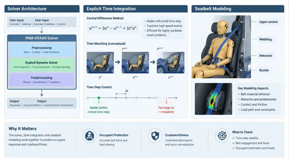
PAM-CRASH is an explicit finite element solver developed by ESI Group, purpose-built for simulating the transient, highly nonlinear events that define vehicle crashworthiness. Unlike implicit solvers that assemble and invert a global stiffness matrix at every load step, PAM-CRASH advances the solution through a central-difference time integration scheme in which the equations of motion are solved directly for nodal accelerations. This architectural choice is what makes it possible to track a full frontal impact — roughly 100–150 ms of physical time involving contact, buckling, rupture, and airbag deployment — within a practical turnaround window.
Solver Architecture and Explicit Time Integration
The core of PAM-CRASH is a Lagrangian structural solver. The mesh moves with the material, and at each time step the solver evaluates internal forces from element stresses, applies external loads (gravity, initial velocity, inflator pressure), and resolves contact interactions between surfaces. The semi-discrete equation of motion is:
M · a(t) = F_ext(t) − F_int(t) + F_contact(t)where M is the lumped mass matrix, a is the nodal acceleration vector, and the right-hand side collects external, internal, and contact forces. Because M is diagonal, no matrix inversion is required — accelerations are obtained by simple division, and velocities and displacements follow from explicit central-difference updates:
v(t+Δt/2) = v(t−Δt/2) + a(t) · Δt
d(t+Δt)   = d(t) + v(t+Δt/2) · Δt
The critical constraint is the Courant–Friedrichs–Lewy (CFL) condition. The stable time step is governed by the smallest element in the model:
Δt_crit = L_min / c, c = √(E / ρ)For a typical steel shell element with characteristic length 5 mm, elastic modulus 210 GPa, and density 7.85 × 10⁻⁹ t/mm³, the wave speed c is approximately 5170 m/s, giving Δt_crit ≈ 0.97 μs. A 120 ms simulation therefore requires on the order of 10⁵ time steps. This is why mass scaling — artificially increasing the density of small elements to raise Δt_crit — is a standard practice, provided the added mass remains below roughly 1–2 % of the total model mass and does not introduce spurious inertia effects.
Why Seatbelt Modeling Matters in Crashworthiness
In a frontal crash, the seatbelt is the primary restraint that couples the occupant to the vehicle deceleration pulse. Its behavior determines how much of the occupant's kinetic energy is absorbed by belt stretch, how the pelvis and thorax are loaded, and whether the head follows a trajectory that the airbag can safely manage. A belt model that is too stiff will over-constrain the chest, producing unrealistically high chest deflection; a belt model that is too soft will allow excessive forward excursion and head strike on the steering wheel or A-pillar.
PAM-CRASH represents the seatbelt using a combination of 1D seatbelt elements (membrane or belt elements) that carry axial tension and slipring elements that allow the belt to slide through the D-ring and buckle anchor. The belt material is typically modeled with a nonlinear elastic-plastic stress–strain curve derived from component tests. Key parameters include:
- Belt stiffness (EA): the product of elastic modulus and cross-sectional area, controlling initial stretch.
- Yield force and elongation: the point at which the belt begins to plastically deform, typically around 4–8 kN for a standard 50 mm polyester webbing.
- Retractor behavior: modeled as a force-limiting or load-limiting element that pays out belt at a controlled force, reducing peak chest loading.
- Pretensioner: a pyrotechnic or motor-driven element that removes slack in the first 10–20 ms, typically pulling 40–80 mm of belt.
- Slipring friction: Coulomb friction at the D-ring and buckle, which affects how tension distributes between the shoulder and lap portions.
The interaction between the belt and the occupant is handled through contact definitions. The belt elements are typically tied to or sliding against a finite element occupant model (e.g., a Hybrid III dummy or a human body model). The contact thickness, friction coefficient, and belt-to-body offset must be calibrated carefully; a 1 mm change in belt offset can alter chest deflection by several millimeters.
Integrated Workflow: From Belt Routing to Injury Criteria
A typical PAM-CRASH occupant safety study follows a sequence that begins with belt routing and ends with injury criteria evaluation. The belt path is defined by anchor points, sliprings, and retractor geometry. The occupant model is positioned according to the seating reference point and the belt is draped over the body. The solver then computes the coupled response: vehicle deceleration is applied as a boundary condition or via a prescribed velocity pulse, the belt engages the occupant, and the occupant loads the belt in return.
Post-processing focuses on injury criteria such as HIC (Head Injury Criterion), chest deflection, chest acceleration (3 ms clip), and femur loads. These are compared against regulatory limits (FMVSS 208, Euro NCAP, or C-NCAP). The belt model directly influences chest deflection and HIC through its force–displacement characteristics and the timing of pretensioner and load-limiter activation.
Calibration and Verification
Before trusting any occupant safety result, the belt model must be calibrated against component-level tests. A standard approach is to simulate a belt pull test — a rigid impactor pulling a section of belt at a prescribed velocity — and compare the force–displacement response with physical test data. The belt stiffness, yield point, and failure strain are adjusted until the curves match within an acceptable tolerance (typically 5–10 % on peak force).
Once the belt is calibrated, a sled test simulation is performed. The sled pulse is applied to the vehicle body, and the occupant response is compared with physical sled test data for head acceleration, chest deflection, and belt force. Discrepancies at this stage usually point to incorrect slipring friction, pretensioner timing, or contact definitions rather than belt material properties.
Key Takeaways for the Modeling Engineer
PAM-CRASH's explicit architecture is well suited to occupant safety because it handles contact, large deformation, and material failure without convergence difficulties. The seatbelt model is not a secondary detail — it is the primary load path between the vehicle and the occupant. Getting it right requires accurate belt material data, realistic slipring and retractor behavior, and careful contact calibration. The time step constraint imposed by the CFL condition means that mesh quality directly affects simulation cost; a single 1 mm element can force a global time step reduction that doubles or triples run time. Engineers should therefore audit mesh quality before adding belt detail, and use mass scaling judiciously with the 2 % rule as a guardrail.
With the solver architecture and belt modeling fundamentals established, subsequent chapters will build on this foundation to cover belt routing, pretensioner and load-limiter modeling, occupant positioning, and injury criteria evaluation in detail.