3. Building a rear impact sled model in PAM
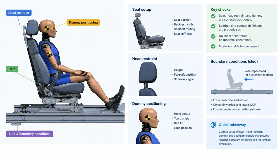
A rear impact sled model is the workhorse of whiplash development. It isolates the seat, head restraint, and occupant from the full vehicle, so you can iterate on geometry and foam properties in hours rather than days. In PAM-CRASH this means assembling four things that must agree with each other: the seat structure, the head restraint, the BioRID-II dummy, and the boundary conditions that drive the sled. Get the interfaces between them wrong and the model will run, but the neck loads will be meaningless.
Coordinate System and Units
Before any geometry is imported, fix the reference frame. PAM-CRASH is unit-agnostic, so declare a consistent set and never mix it. A common convention for occupant safety work is millimetres, tonnes, seconds, and Newtons (mm-t-s-N). In this system:
- X points forward (vehicle travel direction), so a rear impact accelerates the sled in +X.
- Y points to the occupant's left.
- Z points up.
- Rotations follow the right-hand rule about each axis.
The dummy's H-point is the origin of the occupant local frame. All seat and restraint geometry should be positioned relative to this point, because the dummy is placed by its H-point, not by its bounding box. If you later rotate the sled, rotate the whole assembly about the same origin to keep the dummy-seat relationship intact.
Seat Model Construction
The seat is rarely a single part. Decompose it into the structural frame, the cushion and back foam, the recliner, and the trim. The frame carries the load path and should be modelled with shell elements (type 103 or 104 in PAM-CRASH) using an elastic-plastic steel law such as MAT_PLASTIC_KINEMATIC (material 36 equivalent). Foam is the opposite: it is a highly compressible, rate-sensitive material that dominates the dummy's motion in the first 100 ms.
For foam, use solid elements (type 1 or 16) with a crushable foam law. A practical starting point is a stress-strain curve defined by the plateau stress and densification strain. For a typical polyurethane seat foam, an example (illustrative, not measured) curve might be:
Strain   Stress (MPa)
0.00     0.00
0.05     0.08
0.20     0.15
0.50     0.22
0.70     0.45
0.85     1.20
0.95     3.50
The plateau between 0.2 and 0.5 strain is what allows the occupant to sink into the seat. If your foam is too stiff, the dummy will not engage the head restraint; too soft, and it bottoms out against the frame. Mesh the foam with at least three elements through the thickness so the crush gradient is captured. Tie the foam to the frame using a tied contact or shared nodes; a free contact will let the foam slide and produce non-physical gaps.
Head Restraint
The head restraint is the primary countermeasure in a rear impact. Model it as a rigid or elastic body with a defined front surface. The critical parameters are:
- Backset — horizontal distance from the back of the head to the restraint front. Target values below 50 mm are common in modern designs; larger backset delays head contact and increases neck extension.
- Height — the top of the restraint should be at or above the head's centre of gravity. A restraint that is too low lets the head rotate over it.
- Stiffness — the foam or energy-absorbing core determines how the head decelerates. A rigid restraint gives a sharp load spike; a compliant one spreads the load but may allow more extension.
In PAM-CRASH, define the restraint as a separate part with its own material and contact. Use a surface-to-surface contact between the head and the restraint, with a friction coefficient around 0.2–0.3. If the restraint is adjustable, model the locking mechanism as a rigid constraint at the chosen position; do not let it move during the impact unless you are studying adjustment behaviour.
Dummy Positioning
The BioRID-II is the standard rear impact dummy. Its positioning follows a defined procedure, and small errors change neck loads significantly. The key steps are:
- Place the dummy so its H-point matches the seat reference point (SRP) within ±10 mm in X and Z.
- Set the pelvis angle to the seat cushion angle; the pelvis should be in full contact with the cushion and back.
- Adjust the torso to the seat back angle, then set the head to the specified initial angle — typically the head is level or slightly forward.
- Set the neck bracket angle to the value specified by the dummy manufacturer for the test configuration.
- Apply the initial belt or pretensioner state if a belt is present; for a pure whiplash test, the belt may be omitted or slack.
After positioning, run a settling phase of 50–100 ms with gravity applied and the sled stationary. This lets the dummy sink into the foam and reach a stable equilibrium. Check that the dummy's motion during settling is small; if it drifts, the initial position is wrong or the foam is too soft.
Boundary Conditions and Sled Pulse
The sled pulse is the input that drives the model. It is applied as a prescribed acceleration or velocity to the sled base, which is usually a rigid body carrying the seat. A typical rear impact pulse for whiplash testing rises to 8–12 g over 50–80 ms, then decays. The exact pulse depends on the test protocol (e.g., IIWPG, Euro NCAP, or a manufacturer-specific pulse).
In PAM-CRASH, apply the pulse using a LOAD_RIGID_BODY or a prescribed motion on the sled node set. Define the pulse as a time-acceleration curve. The sled base should be constrained in all other degrees of freedom. The seat is attached to the sled via its mounting points; use rigid links or tied contacts at the four floor mounts.
Gravity is applied as a body force in the −Z direction. For a 50th percentile male BioRID-II, the total mass is about 78 kg; the head mass is roughly 4.5 kg. These values matter because the neck loads scale with them.
Model Assembly and Checks
Once the parts are in place, verify the following before running the full simulation:
- No initial penetration between the dummy and the seat or restraint.
- Contact definitions cover all interacting surfaces (head-restraint, torso-seat back, pelvis-cushion).
- Mass and inertia of the dummy match the BioRID-II specification.
- The sled pulse is applied to the correct node set and no other constraints fight it.
- Time step is stable; foam solids often control the step, so check the smallest element.
The SVG below summarises the model architecture and the load path from the sled pulse through the seat to the dummy.
Running and Interpreting the First Result
After the model is assembled, run a short simulation (150–200 ms) and inspect the dummy's head and neck response. The key outputs are:
- Head rotation relative to the torso — the primary whiplash metric. Excessive extension (beyond about 60–70°) indicates the restraint is too far back or too low.
- Neck shear and axial forces at the upper and lower neck. These are compared against injury criteria such as NIC (Neck Injury Criterion) and Nkm.
- Head-restraint contact time — earlier contact reduces extension. If contact occurs after 80 ms, the backset is too large.
If the dummy's head passes over the restraint, check the restraint height first. If the neck loads spike sharply, the restraint is too stiff or the foam is bottoming out. If the dummy slides forward out of the seat, the cushion friction is too low or the pelvis is not properly engaged.
With the sled model built and verified, you have a controlled environment for studying how seat and restraint parameters affect whiplash response. The next step is to introduce the occupant restraint system and the full vehicle boundary, but the sled remains the fastest way to screen design changes.