1. Rear impact and whiplash fundamentals
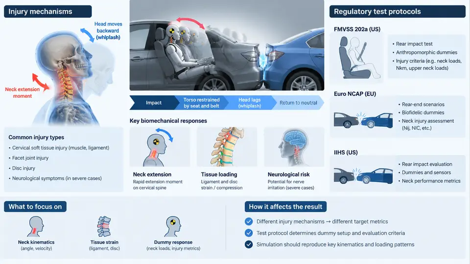
Rear-end collisions are the most frequent crash mode on public roads, and although they are usually low in severity compared with frontal impacts, they generate a disproportionate share of long-term neck injuries. The occupant is struck from behind, the seatback pushes the torso forward, and the head — restrained only by inertia and soft tissue — lags behind. This differential motion between head and torso is the physical origin of whiplash. Understanding the injury mechanism, the biomechanical response of the cervical spine, and the regulatory and consumer test protocols that quantify it is the necessary foundation for any PAM-CRASH rear-impact model.
Injury Mechanisms of the Cervical Spine
Whiplash-associated disorders (WAD) are commonly graded 0–IV under the Quebec classification, from no complaint to fracture or dislocation. In the low-speed regime that dominates real-world rear impacts, the dominant injuries are soft-tissue: capsular strain, facet-joint impingement, and nerve-root irritation. Three kinematic phases define the cervical response during a rear impact:
- Retraction (S-shape): the torso is accelerated forward by the seatback while the head remains nearly stationary. The upper cervical spine extends and the lower cervical spine flexes, producing a transient S-shaped curvature. This phase generates the highest facet-joint shear and capsular strain.
- Extension: the head rotates rearward until the head restraint or neck structures arrest it. Peak extension moment occurs here.
- Rebound (flexion): the head rebounds forward, and the neck flexes. In some cases the rebound excursion exceeds the initial extension.
The key biomechanical quantities are the relative head-to-torso rotation (often called the NIC-related kinematics), the upper-neck extension moment, and the shear force at the occipital condyles. The NIC (Neck Injury Criterion) is defined as:
NIC = 0.2 · a_rel + (v_rel)²

where:
  a_rel = relative horizontal acceleration between T1 and the head CG [m/s²]
  v_rel = relative horizontal velocity between T1 and the head CG [m/s]
  the 0.2 factor has units of s²/m
NIC values above approximately 15 m²/s² are associated with a higher risk of soft-tissue injury in the literature; this threshold is a useful sanity check when post-processing a PAM-CRASH simulation, but it is not a regulatory pass/fail limit.
Biomechanical Response and the Role of the Seat
The seat is the primary interface that shapes the occupant's response. Two design parameters dominate:
- Head restraint geometry: the vertical and horizontal distance between the head restraint and the top of the head. A smaller backset (horizontal gap) and a higher restraint reduce head extension and NIC.
- Seatback stiffness and recliner behaviour: a seatback that yields in a controlled manner absorbs energy and reduces the relative velocity between head and torso, lowering NIC.
In a PAM-CRASH model, these are represented by the seatback foam material model, the recliner joint stiffness, and the head-restraint contact definition. The occupant is typically modelled with a validated BioRID-II or THOR dummy FE model, or with a detailed human body model (HBM) when injury prediction is required.
Regulatory and Consumer Test Protocols
Three protocols dominate rear-impact assessment. They differ in pulse severity, dummy, and criteria, and each imposes different requirements on the simulation setup.
| Protocol | Pulse / Severity | Dummy | Primary Criteria |
|---|---|---|---|
| FMVSS 202a | Delta-V ≈ 17.3 km/h, sled pulse | BioRID-II | Head restraint height/backset; neck injury criteria (NIC, Nij, extension moment) |
| Euro NCAP | Low (≈16 km/h) and high (≈24 km/h) pulses | BioRID-II | NIC, neck extension moment, seatback deflection |
| IIHS | Delta-V ≈ 16 km/h and 32 km/h, two pulses | BioRID-II | Head restraint geometry rating; dynamic criteria (NIC, extension moment) |
FMVSS 202a is a compliance standard: the head restraint must meet static geometry requirements (height ≥ 800 mm, backset ≤ 55 mm) and the dynamic sled test must keep neck injury metrics below specified limits. Euro NCAP and IIHS are consumer rating programmes: they use a star or good/acceptable/marginal/poor rating and are more aggressive in pulse severity and in the weighting of dynamic criteria.
From Protocol to Simulation: A Worked Setup
Consider a Euro NCAP low-severity rear-impact simulation. The steps are:
- Define the pulse: a triangular or trapezoidal acceleration pulse with peak ≈ 4–5 g and duration ≈ 100 ms, applied to the seat base.
- Position the occupant: BioRID-II seated with the H-point at the design position, head restraint backset set to the measured value (e.g. 40 mm), and the seatback angle at the design angle.
- Define contacts: seatback foam, head restraint, and the dummy's back and head surfaces. Friction coefficients are typically 0.3–0.5 for foam–dummy contact.
- Run the simulation and extract the head and T1 accelerations, then compute NIC and the neck extension moment.
- Compare against the protocol limits. If NIC exceeds the threshold, the typical remedies are reducing backset, increasing head restraint height, or softening the seatback.
A common failure symptom is a NIC spike in the first 30–50 ms, which usually indicates that the head restraint is too far back or too low, allowing excessive retraction. Another is a late extension-moment peak, which points to a seatback that is too stiff and returns energy into the occupant during rebound.
The figure summarises the three kinematic phases and the corresponding NIC response. The peak NIC occurs during retraction, before the head restraint is engaged — which is why backset and restraint height are the most influential design variables. In the simulation, the NIC curve should be extracted from the relative head–T1 acceleration and velocity signals, and the peak compared against the protocol threshold. If the peak appears too early or too late relative to the pulse, the seatback stiffness or the contact definition is usually the cause.
With the injury mechanism, the biomechanical metrics, and the three main protocols established, the next step is to translate these requirements into a validated PAM-CRASH model: seat structure, foam, recliner, restraint, and occupant dummy. The remainder of this course builds that model step by step, starting from the seat and occupant positioning and progressing through pulse application, contact definition, and post-processing of the injury criteria introduced here.