1. MADYMO in crash safety engineering
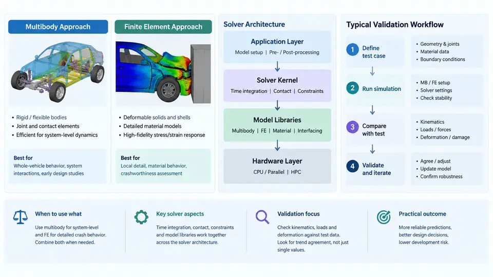
MADYMO (Mathematical Dynamic Model) is a commercial simulation package developed by TASS International (now part of Siemens) that has been a workhorse in occupant safety engineering since the 1970s. Its defining characteristic is a hybrid solver architecture that combines multibody (MB) dynamics with finite element (FE) capabilities in a single simulation environment. Understanding when and why to use each approach — and how they interact — is foundational to building credible crash safety models.
Multibody vs. Finite Element: Complementary Roles
In crash safety engineering, the choice between multibody and finite element methods is not a matter of one being superior; it is a question of matching the modeling fidelity to the physical phenomenon under investigation.
Multibody (MB) approach. Rigid bodies connected by kinematic joints (revolute, translational, spherical, universal, etc.) and force elements (springs, dampers, contact interactions) represent the system. Each rigid body has six degrees of freedom, and the equations of motion are assembled as a system of differential-algebraic equations (DAEs). Because the bodies are rigid, the solver does not need to compute internal deformation, which makes MB simulations extremely fast — typically completing in seconds to minutes on a standard workstation. This speed makes MB ideal for:
- Occupant restraint system design (airbag, seatbelt, seat structure) where the occupant is represented as a chain of rigid segments.
- Parameter studies and design-of-experiments (DOE) campaigns requiring hundreds or thousands of runs.
- Pedestrian protection assessments where the human body model interacts with a vehicle front-end represented by rigid or deformable surfaces.
- Real-time or hardware-in-the-loop (HIL) applications.
Finite Element (FE) approach. The structure is discretized into elements (shells, solids, beams), and the solver computes nodal displacements, strains, and stresses by integrating the weak form of the momentum equation. FE captures large deformations, material nonlinearity, contact, and failure — essential for:
- Vehicle body-in-white (BIW) crashworthiness (frontal, side, rear impact).
- Airbag deployment simulation with folded fabric, gas flow, and venting.
- Material failure and fracture prediction in structural components.
- Detailed component-level validation (e.g., bumper beam, B-pillar).
The trade-off is computational cost: an FE crash model with millions of elements may require hours to days on a high-performance computing (HPC) cluster.
MADYMO Solver Architecture
MADYMO's architecture is built around a single input deck (XML-based since version 7.x) that defines the entire model. The solver processes this deck through several stages:
- Model setup and preprocessing. The input deck specifies bodies, joints, force elements, FE parts, contacts, and boundary conditions. MADYMO checks the model for consistency (e.g., joint definitions, mass properties, initial conditions).
- Time integration. The core solver uses an explicit integration scheme for FE parts and an implicit or explicit scheme for MB bodies, depending on the analysis type. The coupling between MB and FE domains is handled through interface elements that transfer forces and moments at attachment points.
- Contact computation. MADYMO supports multiple contact types: MB-MB (ellipsoid-ellipsoid, plane-ellipsoid), MB-FE (ellipsoid-mesh), and FE-FE (mesh-mesh). Contact forces are computed based on penetration depth and stiffness characteristics.
- Output generation. Results are written to a binary or ASCII output file (e.g.,
.kn3,.dat) containing time-history data for displacements, velocities, accelerations, forces, and energies.
The coupling between MB and FE is a key differentiator. In a typical occupant simulation, the occupant is modeled as an MB system (fast, stable), while the airbag is modeled as an FE mesh (capturing fabric folding and gas dynamics). The two domains exchange forces at the contact interface, allowing the occupant to interact with the deploying airbag without the computational burden of meshing the entire human body.
Typical Validation Workflows
Validation is the process of demonstrating that a simulation model reproduces physical reality with acceptable accuracy. In crash safety engineering, validation is not a single step but a structured workflow:
- Component-level validation. Individual subsystems (e.g., a seatbelt retractor, an airbag module) are tested in isolation and compared against simulation. This isolates modeling errors before they propagate into full-system models.
- Sled test validation. A sled test reproduces the acceleration pulse of a full vehicle crash without destroying the vehicle body. The occupant restraint system is mounted on a sled, and the simulation must match measured occupant kinematics (head, chest, pelvis accelerations) and restraint forces (belt load, airbag pressure).
- Full-scale crash test validation. The complete vehicle model (FE) with occupant (MB) is validated against a full-scale crash test. This is the most comprehensive but also the most expensive validation step.
- Correlation metrics. Quantitative metrics such as CORA (Correlation and Analysis) or ISO/TS 18571 are used to score the agreement between simulation and test curves. A CORA score above 0.8 (on a 0–1 scale) is often considered acceptable for occupant kinematics.
The validation workflow is iterative: discrepancies between simulation and test lead to model updates (e.g., adjusting contact stiffness, material properties, or joint friction), followed by re-simulation and re-evaluation. This loop continues until the correlation metrics meet the project's acceptance criteria.
Practical Considerations for Model Selection
When building a MADYMO model, the following decision framework is commonly applied:
| Scenario | Recommended Approach | Rationale |
|---|---|---|
| Occupant kinematics in a restraint system | MB occupant + FE airbag | Fast occupant simulation; airbag needs FE for deployment |
| Vehicle structural crashworthiness | Full FE | Large deformation, material failure, energy absorption |
| Pedestrian head impact | MB head + FE windshield | Head kinematics fast; windshield fracture needs FE |
| Design of experiments (DOE) | MB only | Hundreds of runs require fast turnaround |
| Seatbelt routing and slip | MB belt + FE seat | Belt slip is kinematic; seat deformation may be nonlinear |
In practice, the most common MADYMO applications in occupant safety use a hybrid model: the occupant is an MB system (often a validated human body model such as the MADYMO Human Body Model or a simplified ellipsoid model), the airbag is an FE mesh, and the seat and interior surfaces may be either MB or FE depending on the level of detail required. The solver handles the coupling automatically, and the analyst controls the fidelity by choosing the appropriate method for each subsystem.
Validation Metrics and Acceptance Criteria
Validation is not a binary pass/fail; it is a quantitative assessment. The CORA (Correlation and Analysis) method, widely used in the automotive industry, evaluates the similarity between two curves (test vs. simulation) based on:
- Corridor rating: How well the simulation curve stays within the test corridor (mean ± standard deviation).
- Phase shift: Time lag between corresponding peaks.
- Magnitude: Difference in peak values.
- Slope: Difference in gradient at key points.
Each metric is scored between 0 and 1, and a weighted average produces the overall CORA score. For occupant safety, a CORA score above 0.8 for head and chest acceleration is typically required for model acceptance. If the score falls below this threshold, the analyst must investigate the source of discrepancy — common causes include incorrect contact stiffness, inaccurate material properties, or misaligned initial conditions.
In summary, MADYMO's strength lies in its hybrid MB-FE architecture, which allows engineers to match modeling fidelity to the physical problem. The validation workflow — from component tests to full-scale crash — ensures that the model is not just computationally efficient but also physically credible. Mastering this balance is the first step toward reliable crash safety simulation.