1. Introduction to MADYMO for airbag deploy
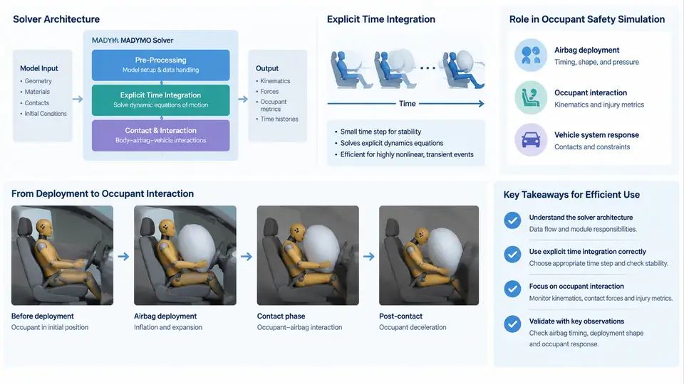
MADYMO (Mathematical Dynamic Model) is a multi-body and finite element solver specialized in occupant safety simulation. It has been used for decades by OEMs, Tier-1 suppliers, and research institutes to predict how an occupant moves and loads during a crash event, and how restraint systems — most notably airbags and seat belts — modify that motion. This chapter establishes the solver architecture, the explicit time integration scheme that drives the simulation, and the specific role MADYMO plays in the occupant safety workflow. These three topics form the foundation for every later chapter on airbag modeling, gas flow, fabric behavior, and occupant interaction.
Solver architecture: multi-body and FE in one environment
MADYMO's defining architectural feature is the tight coupling of two solver domains inside a single time-stepping loop:
- Multi-body (MB) dynamics — rigid bodies connected by kinematic joints (revolute, spherical, translational, bracket, etc.) and force elements (springs, dampers, contact forces). Occupant dummies, seat structures, and steering column components are typically represented this way because they are stiff, articulated, and computationally cheap to integrate.
- Finite element (FE) structures — shell, membrane, solid, and discrete elements for airbag fabrics, folded cushions, inflators, and deformable trim. Airbag deployment is inherently an FE problem: the cushion unfolds, stretches, and contacts the occupant, and these phenomena require a deformable mesh.
The two domains exchange kinematic and kinetic data at every time step through coupling interfaces. An MB dummy hand can contact an FE airbag surface; the contact force is computed on the FE side and applied back to the MB body as a resultant force and moment. This coupling is what makes MADYMO suitable for occupant interaction studies rather than pure structural analysis.
Around the solvers sit several supporting modules: a pre-processor for model assembly, a gas-flow module (uniform-pressure, hybrid, or CFD-based) for inflator output, a contact engine that handles MB-MB, MB-FE, and FE-FE interactions, and a post-processor for occupant kinematics, injury criteria, and energy plots. Understanding which module owns which behavior is essential when debugging a model that fails to deploy or produces unrealistic contact forces.
Explicit time integration
MADYMO uses an explicit time integration scheme, typically the central difference method, to advance the solution. For a multi-body system the equation of motion is:
M · a(t) = F_ext(t) − F_int(t) + F_contact(t)where M is the mass matrix, a is the acceleration vector, and the right-hand side collects external loads, internal joint/spring forces, and contact forces. Because M is diagonal (or block-diagonal for FE), no matrix inversion or factorization is required — the acceleration is obtained by simple division. Velocities and positions are then updated explicitly:
v(t+Δt/2) = v(t−Δt/2) + a(t) · Δt
x(t+Δt)   = x(t) + v(t+Δt/2) · Δt
The critical consequence is the Courant–Friedrichs–Lewy (CFL) stability condition. The time step must satisfy:
Δt ≤ Δt_crit ≈ L_min / cwhere L_min is the smallest element characteristic length and c is the wave speed in the material. For a typical airbag fabric with a 5 mm element and a wave speed of about 100 m/s, Δt_crit is on the order of 5×10⁻⁵ s. MADYMO automatically computes and reports the critical time step; if the user sets a larger value, the simulation will diverge with characteristic symptoms: element distortion, negative volumes, and explosive energy growth.
Explicit integration is chosen for three reasons. First, airbag deployment involves rapid, highly nonlinear contact and large deformation, which implicit methods handle poorly. Second, the physical event is short (50–200 ms), so the small time step is acceptable. Third, the method parallelizes well across CPU cores, which matters when a full vehicle model contains millions of elements.
Role in occupant safety simulation
In the broader CAE workflow, MADYMO occupies the restraint-system and occupant-response stage. A typical project sequence is:
- Crash pulse and vehicle deceleration are obtained from a full-vehicle FE simulation (e.g., LS-DYNA) or from a sled test.
- The pulse is applied to a MADYMO model containing the seat, restraint system, airbag, and occupant dummy.
- MADYMO predicts occupant kinematics, belt loads, airbag contact pressure, and injury criteria such as HIC, chest deflection, and femur force.
- Results feed back into restraint tuning — inflator mass flow, vent size, tether length, fold pattern, and belt geometry.
MADYMO's value here is speed and parametric flexibility. A single run of a sled model may take minutes rather than hours, enabling design-of-experiments studies across dozens of inflator and fold variants. The same model can be switched between a 50th-percentile male, 5th-percentile female, and child dummy by swapping the occupant file, which is essential for regulatory and consumer-rating coverage.
The figure below summarizes the architecture and data flow described above, from the crash pulse input through the coupled MB/FE solvers to the occupant response outputs.
What this means in practice
When you build your first MADYMO airbag model, three practical implications follow directly from the architecture and integration scheme. First, mass scaling and element size control the time step, so a single tiny element in the airbag mesh can slow the entire simulation — check the reported critical time step before running. Second, because MB and FE domains are coupled through contact, an airbag that is not properly positioned relative to the dummy will produce zero contact force and an unbelted occupant will fly through the cushion; always verify the initial gap. Third, the explicit scheme has no equilibrium iteration, so any unphysical initial penetration between the folded airbag and the module housing will generate a large contact force on the first step and can blow up the model. Resolve penetrations in the pre-processor, not by reducing the time step.
With this foundation — coupled MB/FE architecture, explicit central-difference integration, and the restraint-tuning role — the next chapters can focus on the airbag itself: folding, inflator characterization, fabric material models, and the contact algorithms that govern how the cushion interacts with the occupant.