4. Sled test and full-scale crash test faci
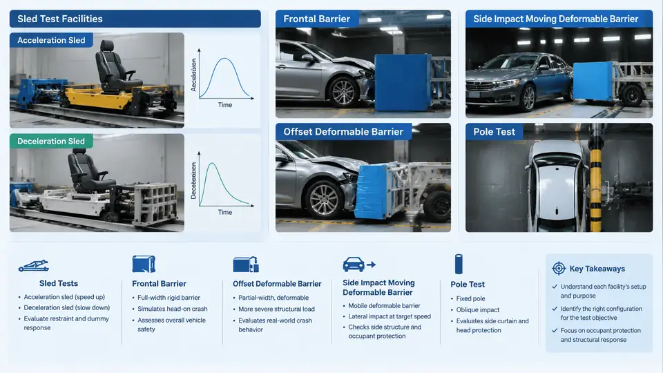
FMVSS occupant protection compliance cannot be demonstrated by analysis alone. Every regulated dynamic requirement — FMVSS 208 frontal air bag and belt performance, FMVSS 214 side impact, FMVSS 201 upper interior head impact, FMVSS 216a roof crush, and FMVSS 305 electric vehicle integrity — is ultimately validated on physical test hardware. The engineer's job is to select the facility whose boundary conditions match the regulation, then control the variables that the regulation does not explicitly fix. This section maps the six principal facility families, their kinematic signatures, and the practical setup decisions that determine whether a test is valid or merely expensive.
Acceleration Sleds: Inertial Loading Without a Vehicle
An acceleration sled holds the body-in-white or a body buck stationary on a carriage and drives the carriage forward with a programmable thrust, so the occupant experiences the same inertial pulse as in a real crash while the structure itself is not crushed. The classic configuration is a HYGE-style servo-hydraulic thruster: a gas-charged accumulator drives a piston whose stroke is shaped by a metering pin, producing a pulse defined by a target velocity change (Δv) and a peak acceleration. A typical FMVSS 208 belted-occupant pulse is Δv ≈ 48 km/h with a peak of 20–25 g and a duration of 90–120 ms.
The key engineering point is that an acceleration sled reproduces the occupant environment, not the vehicle environment. Because the buck does not deform, the restraint system sees a rigid anchor structure. This makes the acceleration sled the correct tool for restraint tuning, air bag timing, and seat structure evaluation, but the wrong tool for assessing intrusion-driven injury. Pulse shaping is done by iterating the metering pin or, on modern electric sleds, by closed-loop control of a linear motor against a recorded vehicle pulse. Validation criterion: the measured carriage acceleration must fall inside the regulation's corridor at every time step, and the integrated Δv must match the target within roughly ±1 km/h.
Deceleration Sleds: Crushing the Structure
A deceleration sled reverses the arrangement. The carriage is accelerated to the target speed and then arrested by a programmable energy-absorbing device — crush tubes, hydraulic dampers, or a water brake. Because the test article is mounted on the carriage and the carriage decelerates, the structure can be allowed to deform against a fixed reaction surface. This is the standard approach for FMVSS 216a roof crush, FMVSS 207/210 seat anchorage, and component-level FMVSS 214 door intrusion work.
Deceleration sleds are also used for the "body block" and "free motion headform" (FMH) tests of FMVSS 201, where a headform is launched at a specified velocity and angle into a trim panel. Here the sled is really a launcher: the headform is propelled at 24 km/h (15 mph) and the resulting HIC(d) is computed from the triaxial accelerometer at the headform CG. The critical setup variables are impact angle, target point location, and headform orientation — all of which must be recorded to ±1° and ±5 mm, because HIC is highly sensitive to where the head strikes a stiff or soft region.
Full-Scale Frontal Barrier and Offset Deformable Barrier
The full-scale frontal test is the reference configuration for FMVSS 208. A complete vehicle is towed into a rigid, flat, perpendicular barrier at 56 km/h (35 mph) with the test dummies belted and, for the unbelted option, positioned per the regulation. The barrier is a fixed concrete block with a steel face plate; the vehicle is aligned to the barrier within ±25 mm laterally and ±1° in yaw. Instrumentation includes accelerometers on the vehicle CG and sill, load cells in the barrier face, and the dummy's head, chest, and femur channels.
The offset deformable barrier (ODB) test, used for FMVSS 208 optional belted/unbelted compliance and for NCAP, replaces the rigid wall with a honeycomb-faced deformable element covering 40% of the vehicle width. The vehicle is driven at 64 km/h (40 mph) with 40% overlap on the driver side. The deformable barrier is a calibrated aluminum honeycomb block with a specified crush strength, so the test measures structural interaction rather than pure rigid-body deceleration. The offset configuration is far more sensitive to body structure design — longitudinal rail collapse, subframe engagement, and wheel intrusion — than the flat barrier, and it is the configuration where restraint and structure must be co-tuned.
Side Impact Moving Deformable Barrier
FMVSS 214 side impact uses a moving deformable barrier (MDB) that strikes a stationary target vehicle. The MDB is a trolley carrying a deformable honeycomb face, with a total mass of 1,368 kg and a face width of 1,676 mm. It is driven at 54 km/h (33.5 mph) into the driver side of the target vehicle, with the barrier's longitudinal axis perpendicular to the vehicle's longitudinal axis. The honeycomb face has six cells with specified crush strengths, so the barrier itself is a calibrated load path.
The target vehicle is stationary with the ES-2re or SID-IIs dummy in the struck-side seat. The critical setup parameters are the vertical alignment of the barrier face to the vehicle's occupant compartment, the lateral impact point (typically aligned to the dummy's H-point), and the barrier's pitch and yaw. A misalignment of even 25 mm vertically can shift the load path from the door beam to the sill and change the measured rib deflection by several millimeters. Post-test, the engineer reads the dummy's rib deflection, abdominal force, and pelvic acceleration, and correlates them with door intrusion measurements taken at the same stations.
Pole Test Configurations
The pole test is a narrow-object impact used for FMVSS 201 side pole (head protection) and for FMVSS 214 optional side pole compliance. A rigid vertical pole of 254 mm diameter is fixed to the ground, and the vehicle is towed sideways into it at 32 km/h (20 mph) with a yaw angle of 75° between the vehicle's longitudinal axis and the pole. The pole is positioned so that it strikes the vehicle at the occupant's head location, typically aligned to the H-point of the struck-side dummy.
The pole test is the most demanding side configuration because the load is concentrated over a small area, producing high local intrusion and a direct head-to-pole path. The setup requires precise control of the pole's vertical position, the vehicle's yaw, and the tow speed. The dummy is an ES-2re or SID-IIs, and the primary injury metric is head injury criterion (HIC) plus rib deflection. Because the pole is rigid, the test isolates the vehicle's side structure and side air bag performance from the barrier's own compliance.
Facility Selection and Cross-Facility Consistency
The table below summarizes the six configurations and their primary compliance targets.
| Facility | Kinematic signature | Primary FMVSS use | Key setup variable |
|---|---|---|---|
| Acceleration sled | Programmed forward pulse, rigid buck | 208 restraint tuning, 207/210 | Pulse corridor, Δv |
| Deceleration sled | Programmed deceleration, deforming article | 216a roof crush, 201 FMH | Crush tube profile, impact angle |
| Frontal rigid barrier | Full vehicle, 56 km/h, 0° | 208 belted/unbelted | Alignment, dummy position |
| Offset deformable barrier | 40% overlap, 64 km/h | 208 optional, NCAP | Honeycomb crush strength |
| Side MDB | 1,368 kg trolley, 54 km/h, 90° | 214 side impact | Vertical/lateral impact point |
| Side pole | 254 mm rigid pole, 32 km/h, 75° yaw | 201 side pole, 214 optional | Pole-to-H-point alignment |
The engineering discipline across all six facilities is the same: define the reference frame first, control the alignment and pulse variables that the regulation leaves open, and verify the measured response against the corridor before interpreting occupant injury metrics. A test that passes the dummy channels but misses the pulse corridor or the impact point is not a compliance test — it is a data point that must be repeated.