1. Course overview
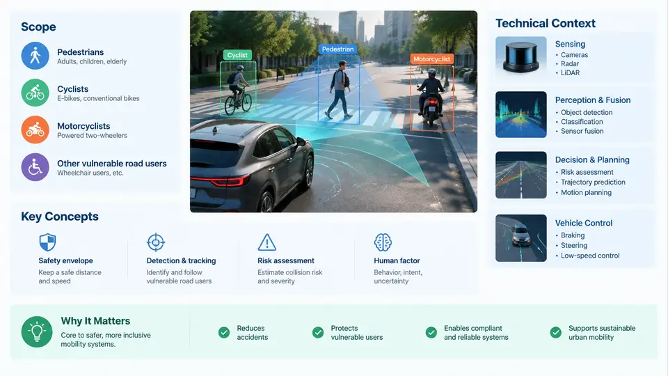
Automotive pedestrian and vulnerable road user (VRU) protection is the engineering discipline concerned with reducing the severity of injury when a vehicle interacts with a human body outside the vehicle. It sits at the intersection of vehicle body design, crash mechanics, sensing and perception, active safety control, biomechanics, and regulation. This chapter establishes the vocabulary, the physical problem, the regulatory and rating landscape, and the technical architecture that the remaining 29 chapters build upon.
1.1 Who Counts as a Vulnerable Road User
The term Vulnerable Road User is defined by the absence of a protective shell. ISO 39001 and the European Commission's road-safety framework group pedestrians, cyclists, motorcyclists, and users of powered two-wheelers under this umbrella, and increasingly include e-scooter riders and persons in wheelchairs. What unites them is not their mode of transport but their exposure: an unprotected human body absorbing kinetic energy directly from a vehicle structure.
For engineering purposes, VRU protection is usually split into two distinct problem classes:
- Pedestrian protection — the standing or walking human struck by the front of a vehicle. The dominant injury mechanisms are head impact against the hood or windshield, and leg/knee impact against the bumper and grille.
- Cyclist and two-wheeler protection — a rider with a bicycle or motorcycle between them and the car. The kinematics differ substantially: the struck object has its own mass, geometry, and degrees of freedom, and the rider is often thrown onto the roof or over the rear of the vehicle.
This course treats pedestrian protection as the primary thread because it drives the majority of regulatory test procedures, then extends the same physical and sensing principles to cyclists and other VRUs.
1.2 The Physical Problem: Energy, Geometry, and Time
A pedestrian struck at 40 km/h (11.1 m/s) by a 1,500 kg vehicle carries a relative kinetic energy of roughly 92 kJ at the moment of contact. The human body cannot absorb this without injury. The engineering objective is therefore not to prevent all injury but to manage the energy transfer: reduce impact speed before contact, deform vehicle structures in a controlled manner, and avoid concentrating force on the head and lower limbs.
Three physical quantities govern the outcome:
| Quantity | Typical value / range | Engineering relevance |
|---|---|---|
| Impact speed | 20–60 km/h in urban crashes | Head injury risk rises steeply above ~30 km/h; AEB must intervene below this |
| Head impact velocity | 6–12 m/s relative to vehicle | Directly drives HIC; controlled by hood deformation and windshield stiffness |
| Bumper lead / hood height | 60–120 mm lead; 700–1,050 mm hood leading edge | Determines whether the leg bends or fractures and where the head lands |
The Head Injury Criterion (HIC) is the standard scalar metric. It integrates resultant head acceleration over a time window:
HIC = [ (1/(t2 - t1)) * ∫ a(t) dt ]^2.5 * (t2 - t1)
      evaluated over the window that maximizes the result, capped at 36 ms
Regulatory limits are typically HIC ≤ 1,000 for the adult headform and HIC ≤ 1,700 for the child headform in the same test, though Euro NCAP applies stricter thresholds for higher ratings. The exponent 2.5 means that a 20% increase in average acceleration raises HIC by roughly 58% — a nonlinearity that explains why small design changes matter.
1.3 Active, Passive, and Integrated Protection
VRU protection is delivered by two complementary layers, and modern vehicles integrate them.
Passive (secondary) protection acts after contact. It includes energy-absorbing bumper beams, deformable hood inner panels, active hood lifters that raise the hood by 60–100 mm to create a deformation gap above the engine, windshield airbag systems, and pedestrian-friendly headlamp and grille geometry. These measures are validated by impactor tests: the legform, upper legform, and adult/child headform are fired at the vehicle at defined speeds and angles.
Active (primary) protection acts before contact. Forward-facing radar, camera, and lidar detect pedestrians and cyclists, and the ADAS controller issues a warning, applies partial braking, or commands full autonomous emergency braking (AEB). A typical pedestrian AEB stack runs perception at 20–50 Hz, tracks the object, predicts a collision time (TTC), and triggers braking when TTC falls below a calibrated threshold — commonly 1.2–1.8 s for warning and 0.6–1.0 s for full braking, depending on vehicle speed and road friction estimate.
1.4 Regulatory and Rating Context
Three frameworks shape the engineering targets:
- UN Regulation No. 127 (formerly UN R127, derived from GTR No. 9) — mandates pedestrian legform and headform impactor tests for type approval in signatory markets. It defines impactor mass, velocity, and impact points.
- Euro NCAP — goes beyond regulation with stricter HIC limits, cyclist test scenarios, AEB VRU test protocols (car-to-pedestrian near-side, far-side, and car-to-cyclist), and a separate VRU protection rating.
- China NCAP and other regional programs — increasingly align with Euro NCAP but adjust scenarios for local traffic patterns, such as higher two-wheeler density.
The practical consequence is that a vehicle designed only to pass UN R127 may still score poorly in Euro NCAP, because the rating adds cyclist scenarios, night-time AEB, and reverse AEB. Engineers must therefore design to the union of requirements, not the minimum.
1.5 System Architecture Overview
The figure below shows how the active and passive layers connect in a modern vehicle, from sensing through decision to actuation and structural response.
1.6 What This Course Covers
The remaining chapters follow a deliberate progression. Chapters 2–6 establish the biomechanics of pedestrian injury, the kinematics of the struck body, and the injury metrics used in regulation. Chapters 7–12 cover passive countermeasures: bumper and legform design, hood and fender geometry, active hood systems, and windshield interaction. Chapters 13–20 address active safety: sensor selection, perception algorithms, AEB control logic, test protocols, and failure modes such as occlusion and adverse weather. Chapters 21–26 examine cyclist and two-wheeler scenarios, where the struck object's own dynamics change the problem. Chapters 27–30 cover validation, simulation (finite element human body models and impactor FE models), regulatory documentation, and emerging trends such as external airbags and vehicle-to-pedestrian communication.
1.7 The Engineering Mindset
VRU protection is unusual in automotive engineering because the "customer" is outside the vehicle and has no purchase decision. This creates a design tension: pedestrian-friendly front ends (higher hood, softer bumper, more deformation space) conflict with styling, aerodynamics, and underhood packaging. The engineer's job is to find the feasible region where regulatory compliance, rating performance, and vehicle attributes coexist.
A useful mental model is the injury risk chain: vehicle speed → impact energy → body kinematics → tissue loading → injury. Every countermeasure interrupts this chain at a specific link. AEB interrupts at the first link by reducing speed. Bumper design interrupts at the second by absorbing energy. Hood deformation interrupts at the fourth by limiting head acceleration. Understanding which link a given measure addresses prevents the common mistake of expecting a single technology to solve the whole problem.
With this framework in place, Chapter 2 begins with the biomechanics of the human body under impact — the physical basis for every threshold, test, and design decision that follows.