1. Introduction to human body models in inj
Injury biomechanics answers a deceptively simple question: for a given physical insult — a deceleration pulse, a door intrusion, a blunt impact — what loads reach which tissues, and will those tissues fail? Human body models (HBMs) are the computational instruments we use to answer that question before a physical test exists, or to explain a physical test after the fact. In a design context, an HBM is not a research curiosity; it is a decision tool that sits between a crash pulse or a product geometry and a pass/fail judgement about occupant or pedestrian safety.
The key word is decision. A model earns its place in a design loop only when its predictions are credible enough to change a design choice — a restraint anchor location, a hood inner-panel stiffness, a seat-pan ramp angle. That credibility is never absolute. It is always conditional on the loading regime, the body region, and the validation evidence behind the model. Understanding that conditionality is the central skill this chapter introduces.
Where HBMs Sit in the Design Decision Chain
A typical vehicle or protective-equipment programme moves through concept geometry, CAE iteration, physical sled or component testing, and finally certification. HBMs occupy the CAE iteration stage and increasingly the certification stage, where regulatory and consumer-rating protocols (for example frontal offset and pedestrian-leg subsystem tests) accept validated FE models as evidence. The model's output — head acceleration, chest deflection, femur force, knee bending moment — is compared against injury criteria such as HIC, chest compression, or tibia index. The design decision is then made on the margin between the predicted value and the criterion threshold.
This means an HBM must be understood at three levels simultaneously: the anatomical fidelity of its geometry and material properties, the numerical fidelity of its solver setup (element formulation, hourglass control, contact definitions, time step), and the validation fidelity — the experiments against which its predictions have been compared. A model can be anatomically exquisite and still be useless for a given question if it has never been validated under that loading mode.
The Three Model Families
Three families dominate practice, and they are complementary rather than competing.
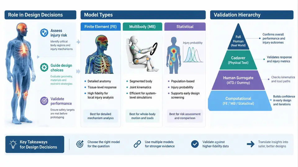
Finite element (FE) models discretise anatomy into solid, shell, and beam elements with constitutive laws for bone, cartilage, ligament, muscle, and brain tissue. They resolve local stress and strain fields and are the only family that can predict tissue-level injury in regions without a well-established external criterion. Their cost is high: a detailed full-body FE model may contain one to two million elements and require hours to days per run, and its material parameters for soft tissue are often the least certain part of the model.
Multibody models represent the body as rigid segments joined by kinematic joints with stiffness and damping, often with contact definitions for external surfaces. They run in seconds to minutes, which makes them ideal for design-space exploration, parameter sweeps, and real-time or hardware-in-the-loop applications. They predict gross kinematics and joint loads well but cannot resolve tissue-level strain; they are the right tool when the question is "where does the head go" rather than "what strain does the corpus callosum see."
Statistical and injury-risk models are not body models in the geometric sense at all. They are regression or survival models — logistic regression, Weibull survival, or machine-learned classifiers — fitted to experimental or field data, mapping an external or internal load measure to a probability of a given injury severity (commonly AIS 2+). They are fast, transparent, and directly probabilistic, which suits fleet-level or population-level design targets, but they are only valid inside the parameter range of their source data and cannot explain why an injury occurs.
| Family | Typical output | Run cost | Best-suited design question | Principal limitation |
|---|---|---|---|---|
| FE | Stress, strain, tissue-level injury metrics | Hours to days | Local tissue injury; restraint interaction detail | Soft-tissue material uncertainty; computational cost |
| Multibody | Segment kinematics, joint loads, contact forces | Seconds to minutes | Design-space sweeps; kinematic trade studies | No tissue-level strain resolution |
| Statistical | Injury probability vs. load measure | Instantaneous | Population risk targets; criterion calibration | Valid only within source-data range; no mechanism |
The Validation Hierarchy
No HBM is validated as a whole. It is validated bottom-up, and the credibility of a whole-body prediction rests on the credibility of each level beneath it. The hierarchy typically runs: material coupon tests (tissue and bone specimens under controlled strain rate), component tests (a single femur, a rib cage, a skull), subsystem tests (thorax plus spine, pelvis plus femur), full-body PMHS (post-mortem human subject) tests, and finally field or volunteer data for the low-severity regime. Each level constrains different parameters, and a model that matches full-body kinematics while its rib material is unvalidated is a model whose chest-deflection predictions should not be trusted.
Two practical consequences follow. First, when you select an HBM, ask which levels of the hierarchy have been exercised for your loading mode, not merely how many publications cite the model. Second, when a model disagrees with a physical test, the hierarchy tells you where to look: a kinematic mismatch points to subsystem or full-body boundary conditions, while a tissue-level mismatch with correct kinematics points down to material or component level.
Reading the Model Landscape
The figure below maps the three model families against the validation hierarchy and the design decision they feed. Read it left to right as the flow from physical evidence to design action, and note that the statistical family draws its data from the same experimental levels that validate the FE and multibody models — the families share an evidence base even though they consume it differently.
Choosing a Model for a Real Decision
Consider a concrete example. A team is evaluating a new knee bolster geometry intended to reduce lower-extremity injury in a frontal offset impact. The design question is whether the revised bolster reduces femur force and knee bending moment below the chosen criteria without increasing chest deflection through a changed load path.
The first decision is model family. Because the question involves both local contact force at the knee and a coupled chest response, a full-body FE model is appropriate for the final assessment, but a multibody model is the efficient tool for the initial geometry sweep across bolster depth and angle. The statistical family enters later, when the team wants to translate the predicted femur forces into a population injury-risk estimate for the target occupant range.
The second decision is validation relevance. The FE model's lower-extremity predictions should be checked against component-level femur and knee tests and against full-body PMHS sled tests with comparable belt and bolster loading. If the model has only been validated for belt-only loading without a knee bolster contact, its femur-force predictions in the new configuration carry an unquantified uncertainty, and the design margin should be widened accordingly — or a component test should be added to close the gap.
What This Course Builds On
The chapters that follow develop each of these threads in depth: the anatomy and material behaviour that constrain FE models, the kinematic and contact formulations behind multibody models, the statistical methods that convert loads into risk, and the validation and uncertainty-quantification practice that determines how much confidence a design team may place in any prediction. The organising principle throughout is the same one introduced here — a model is only as credible as the validation evidence relevant to the question being asked, and the design decision must be framed so that the model's limitations are visible in the margin.