1. Enterprise crash CAE platform landscape
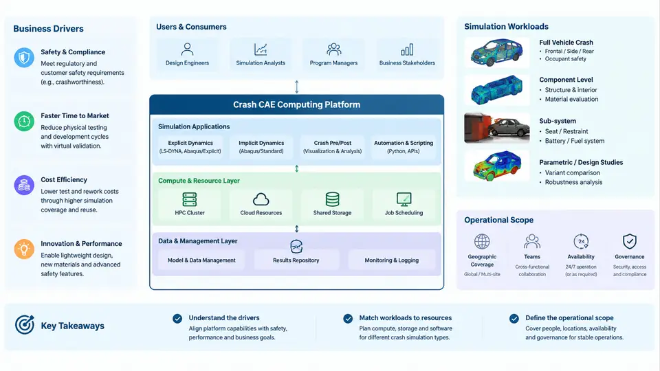
An enterprise crash CAE platform is not simply a cluster running LS-DYNA. It is a socio-technical system that connects vehicle program milestones, regulatory and consumer-test requirements, solver licensing, HPC capacity, data governance, and the engineers who interpret results. Before discussing job submission, queue tuning, or solver debugging, an operations engineer must understand why the platform exists, what workloads it carries, and where the operational boundary lies. This chapter establishes that landscape.
Business Drivers That Shape the Platform
Crash simulation sits on the critical path of vehicle development. A typical full-vehicle frontal impact model contains 8–15 million elements, runs for 8–30 wall-clock hours on 128–512 cores, and must be repeated dozens of times per program as the body-in-white, restraints, and battery enclosure evolve. The business drivers that determine platform requirements are therefore concrete:
- Program timing. A vehicle program may require 300–800 crash load cases across frontal, side, rear, pole, and pedestrian scenarios. If each iteration takes two days instead of one, the program slips by weeks.
- Regulatory and rating compliance. FMVSS 208, FMVSS 214, Euro NCAP, and C-NCAP define mandatory and rating load cases. Each has prescribed boundary conditions, dummy models, and injury criteria (HIC, chest deflection, femur load), which the platform must support reproducibly.
- Cost of physical testing. A single sled or full-vehicle crash test costs tens of thousands of dollars and consumes a prototype. Simulation replaces most iterations, so platform availability directly protects prototype budget.
- Licensing economics. LS-DYNA, PAM-CRASH, and Radioss tokens are expensive. Idle licenses and over-subscribed queues both waste money; the platform must balance utilization against turnaround.
These drivers translate into non-functional requirements: high core-count throughput, deterministic turnaround for priority jobs, traceable model and result versions, and audit-ready evidence for certification submissions.
Simulation Workloads on the Platform
Crash CAE workloads are not homogeneous. They differ in solver, model size, parallel scalability, memory footprint, and I/O pattern. Understanding this mix is essential because it determines queue design, storage tiering, and node sizing.
| Workload class | Typical solver | Model size | Cores | Wall time | Dominant resource |
|---|---|---|---|---|---|
| Full-vehicle frontal/side | LS-DYNA SMP/MPP | 8–15 M elements | 128–512 | 8–30 h | Memory bandwidth, interconnect |
| Sled / subsystem | LS-DYNA, PAM-CRASH | 1–3 M elements | 32–96 | 1–4 h | CPU, license tokens |
| Occupant restraint (MADYMO) | MADYMO, LS-DYNA | 0.1–0.5 M elements | 8–32 | 0.5–2 h | Single-thread performance |
| Pedestrian protection | LS-DYNA | 2–5 M elements | 64–192 | 3–10 h | Contact, CPU |
| Battery pack crush | LS-DYNA, Abaqus/Explicit | 3–8 M elements | 96–256 | 6–20 h | Memory, contact |
| Design of Experiments sweeps | LS-DYNA (many small jobs) | 0.5–2 M elements | 16–64 each | 0.5–3 h each | Scheduler throughput |
Two operational consequences follow. First, MPP (massively parallel processing) jobs with 256+ ranks are sensitive to interconnect latency and to how the decomposition is performed; a poorly balanced model can lose 30–40% of its theoretical speedup. Second, DOE sweeps generate hundreds of short jobs that stress the scheduler and license server far more than they stress compute nodes. A platform tuned only for large jobs will choke on sweeps, and vice versa.
Operational Scope: What the Platform Team Owns
The operational scope defines the boundary between the CAE platform team and its users (crash analysts, method developers, IT infrastructure). A clear boundary prevents both gaps and duplicated effort.
Inside scope: HPC cluster and scheduler (Slurm, PBS Pro, or LSF), solver installation and license brokering, shared parallel filesystem, job submission portals and templates, queue policy and fair-share configuration, model/result data lifecycle, monitoring and alerting, and user support for job failures.
Outside scope (but interfaced): CAD/PLM data management, meshing and model assembly (owned by analysts), material card calibration, correlation with physical tests, and corporate identity/network services.
The interface points are where most operational incidents originate. For example, a model assembled in a PLM-managed workspace may reference include files via absolute paths that do not exist on compute nodes. The platform team does not own the model, but it must provide a predictable filesystem layout and validate job inputs before they consume 256 cores for two hours.
Reference Architecture
The following diagram shows the logical layers of an enterprise crash CAE platform and the primary data and control flows between them. It is a structural view, not a deployment diagram: the same logical layer may span multiple physical clusters or sites.
From Landscape to Daily Operations
With the landscape established, the operational questions become concrete. When an analyst reports that a frontal impact job ran 40% slower than the previous revision, the platform engineer must be able to trace the cause across layers: Was the model decomposed differently? Did the job land on nodes with degraded InfiniBand links? Was a license token shortage forcing a smaller rank count? Was the parallel filesystem under contention from a concurrent DOE sweep?
Answering such questions requires baseline data. A minimal but effective baseline for a crash CAE platform includes:
- Per-job metrics: job ID, user, solver, rank count, node list, queue wait time, run time, exit status, peak memory per node, license tokens consumed.
- Per-model metrics: element count, include file count, total input size, decomposition method, contact count.
- System metrics: node CPU utilization, memory pressure, interconnect error counters, filesystem throughput and metadata operations per second.
These metrics are not collected for their own sake. They feed the three operational decisions that dominate day-to-day work: queue and priority tuning, capacity planning, and failure triage. A platform without baseline metrics can only react; a platform with them can predict that the next program's 400 additional load cases will exhaust the current node pool in week six, and can justify procurement before the schedule is at risk.