1. Cross-solver CAE model transferability a
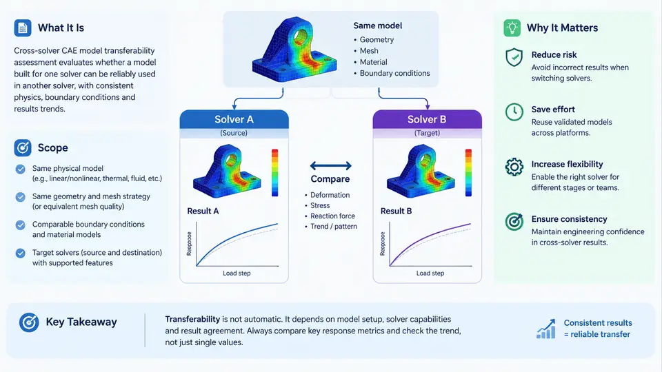
In modern product development, a single CAE model rarely stays inside one solver. A crashworthiness model authored in LS-DYNA may need to be re-evaluated in Abaqus/Explicit for a supplier audit; a CFD mesh built for Fluent may be handed to STAR-CCM+ after a corporate tool consolidation; a structural model tuned in Nastran may be migrated to OptiStruct for topology optimization. Each of these moves raises the same engineering question: does the model still predict the same physics after it crosses the solver boundary? Cross-solver CAE model transferability assessment is the disciplined process of answering that question with evidence rather than assumption.
What Transferability Actually Means
Transferability is not the same as file convertibility. A translator can produce a syntactically valid input deck in the target solver while silently changing the meaning of the model. Transferability is a behavioral property: the transferred model must reproduce the reference model's response within an explicitly declared tolerance, across a declared set of load cases, for a declared set of output quantities.
Formally, let Rref be the response vector produced by the source model in the source solver, and Rtgt the response vector produced by the transferred model in the target solver, both evaluated on the same physical scenario. Transferability holds when
|| R_tgt - R_ref || / || R_ref || <= epsilon, for all load cases in the assessment setwhere epsilon is a project-agreed tolerance, typically 2–5% for global quantities such as peak force or first natural frequency, and tighter (1–2%) for quantities that drive a safety margin. The norm, the load-case set, and the tolerance are all part of the assessment definition — without them, "the model transferred fine" is an opinion, not a result.
Scope: What Falls Inside the Assessment
A complete transferability assessment covers four layers, and skipping any one of them is the most common source of late-stage surprises.
- Topology and connectivity. Element types, node-to-node connectivity, rigid body definitions, tie constraints, and contact pairings. A shell that becomes a solid, or a tied interface that becomes a free surface, changes the load path entirely.
- Material and section definitions. Constitutive law mapping (for example,
*MAT_PIECEWISE_LINEAR_PLASTICITYin LS-DYNA versus*PLASTICin Abaqus), strain-rate dependence, failure criteria, and section integration rules. - Boundary conditions and loads. Constraint equations, prescribed motion, initial velocity fields, gravity, and time-dependent amplitude curves. Unit systems must be reconciled explicitly — a model in mm/ms/kg versus one in m/s/kg differs by factors of 103 in force and 106 in energy.
- Solution controls. Time integration scheme, time-step control, mass scaling, contact stiffness, and convergence criteria. These are solver-specific and often the dominant cause of divergence between otherwise identical models.
Anything outside these four layers — meshing quality, geometry cleanup, post-processing scripts — is usually treated as shared infrastructure, but it still needs to be frozen during the assessment so that observed differences can be attributed to the solver transfer rather than to a mesh change.
Why This Matters: Engineering Motivation
The motivation is not academic. Three pressures make cross-solver transferability a first-class engineering concern.
Tool consolidation and supply-chain heterogeneity. OEMs and Tier-1 suppliers frequently operate different solver stacks. A crash pulse validated in one solver must be defensible when the same model is re-run by a partner using a different explicit code. Without a transferability assessment, the partner's result may differ by 10–15% in peak intrusion, and the discrepancy surfaces during a design review rather than during a controlled study.
Regulatory and certification evidence. Safety-critical submissions require traceable model provenance. If a model is migrated between solvers, the burden of proof is on the engineer to demonstrate equivalence. A documented assessment with declared tolerances and load cases is the evidence that satisfies that burden.
Cost and schedule. Rebuilding a model from scratch in a new solver can consume weeks of engineering time and introduce fresh modeling errors. A validated transfer preserves the invested modeling effort and shortens the requalification cycle. Conversely, an unvalidated transfer that fails late in a program can cost far more than the assessment itself.
The Assessment Workflow at a Glance
The figure below shows the core structure of a transferability assessment: a frozen reference model is executed in the source solver, translated into the target solver, executed again on identical load cases, and the two response sets are compared against declared tolerances. The decision gate determines whether the transfer is accepted, requires correction, or is rejected.
What a Minimal Assessment Deliverable Looks Like
The following table is a compact, fillable assessment record. It is deliberately small: one row per load case, one column per critical output quantity. In practice, a crash model might have 5–10 load cases and 4–8 output quantities, but the structure stays the same.
| Load Case | Output Quantity | R_ref (source) | R_tgt (target) | Relative Error | Tolerance ε | Status |
|---|---|---|---|---|---|---|
| Frontal 50 km/h | Peak B-pillar intrusion (mm) | 142.3 | 145.1 | 1.97% | 3% | Pass |
| Frontal 50 km/h | Peak force (kN) | 318.5 | 341.2 | 7.13% | 5% | Fail |
| Side pole 32 km/h | Max door velocity (m/s) | 8.42 | 8.51 | 1.07% | 3% | Pass |
| Modal (free-free) | 1st natural frequency (Hz) | 28.6 | 28.4 | 0.70% | 2% | Pass |
In this illustrative example, the peak force discrepancy of 7.13% exceeds the 5% tolerance. The correct response is not to widen the tolerance but to isolate the cause. The most likely candidates are contact stiffness defaults, strain-rate material mapping, or mass-scaling settings — all solution-control layer items. The assessment record makes that investigation targeted rather than speculative.
Key Takeaways
- Transferability is behavioral equivalence within a declared tolerance, not file convertibility.
- The assessment scope covers four layers: topology/connectivity, material/section, boundary conditions/loads, and solution controls.
- Freeze everything except the solver; otherwise discrepancies cannot be attributed.
- Declare tolerances per output quantity and per load case before running the comparison.
- When a quantity fails, investigate the responsible layer rather than relaxing the criterion.
With these definitions and scope established, the next step is to examine the specific mapping mechanisms — element formulation, constitutive law translation, and contact algorithm differences — that determine whether a transfer will pass or fail.