3. Parametric geometry generation
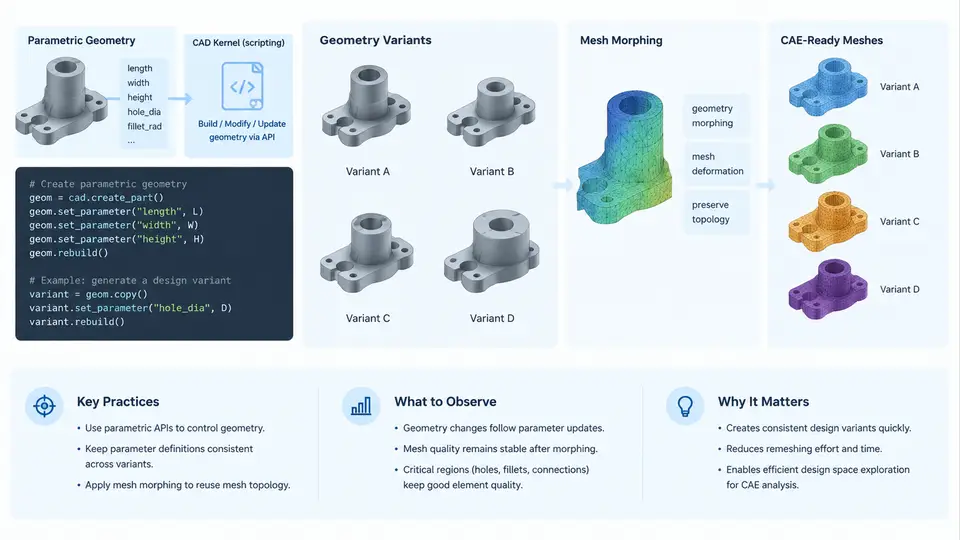
Design space exploration (DSE) only becomes meaningful when the geometry itself can change. A single baseline CAD model, no matter how well meshed, gives you one data point. To sweep a design space you need a repeatable pipeline that turns a vector of design parameters into a valid, analysis-ready geometry — and does so hundreds or thousands of times without manual intervention. This chapter covers the two dominant strategies for that pipeline: parametric CAD scripting against a kernel API, and mesh morphing applied directly to an existing discretized model.
Why the Geometry Layer Is the Bottleneck
In a typical CAE workflow, geometry creation and cleanup consume the largest share of wall-clock time. When you automate the solver but still rebuild geometry by hand, the automation is only partial. The goal of parametric geometry generation is to make the geometry a pure function of the parameter vector:
geometry = f(p1, p2, ..., pn)If that function is deterministic, scriptable, and robust across the parameter ranges you intend to explore, then the entire DSE loop — sampling, meshing, solving, post-processing — can run unattended. If it is not, every failed variant becomes a manual repair task, and the sweep collapses.
Approach 1: Scripting a CAD Kernel
Most professional CAD systems expose a scripting interface to their geometric modeling kernel. Examples include the OpenCASCADE-based APIs used by FreeCAD and pythonocc, the Parasolid or ACIS APIs behind commercial tools, and the feature-level APIs of SolidWorks, CATIA, and NX. The pattern is consistent: you construct primitives, apply Boolean operations, fillet or chamfer edges, and export a neutral format such as STEP or a native mesh.
A minimal parametric bracket in pythonocc illustrates the structure. The design parameters are plate length L, plate width W, thickness t, and hole radius r:
from OCC.Core.BRepPrimAPI import BRepPrimAPI_MakeBox
from OCC.Core.BRepAlgoAPI import BRepAlgoAPI_Cut
from OCC.Core.BRepPrimAPI import BRepPrimAPI_MakeCylinder
from OCC.Core.STEPControl import STEPControl_Writer

def make_bracket(L, W, t, r):
    plate = BRepPrimAPI_MakeBox(L, W, t).Shape()
    hole  = BRepPrimAPI_MakeCylinder(r, t).Shape()
    # translate hole to plate center, then subtract
    ...
    return BRepAlgoAPI_Cut(plate, hole).Shape()
The critical engineering concerns are not the API calls themselves but the robustness envelope. A fillet that succeeds at r = 2 mm may fail when the adjacent wall thins below the fillet radius. A Boolean cut may produce a non-manifold solid when the hole breaks through an edge. These are not bugs in your script — they are geometric constraints that define the feasible region of your design space. Your sampling strategy must respect them, or your pipeline must detect and reject invalid variants gracefully.
None on kernel failure, and log the parameter vector that caused it. A sweep that silently drops 30% of its samples produces a biased surrogate model.
Approach 2: Mesh Morphing
When the topology of the model does not change — same number of holes, same connectivity, same boundary conditions — mesh morphing is often faster and more robust than rebuilding CAD. Instead of regenerating geometry, you displace the existing mesh nodes according to a parameterized deformation field. The mesh connectivity is preserved, so the solver input remains valid without remeshing.
Common morphing formulations include:
- Free-Form Deformation (FFD): embed the mesh in a control lattice; move lattice control points to deform the enclosed geometry.
- Radial Basis Functions (RBF): interpolate displacements from a set of control points using a smooth kernel such as a thin-plate spline.
- Laplacian / elasticity smoothing: propagate boundary displacements into the interior by solving a smoothing or linear-elasticity problem on the mesh graph.
An RBF morph is defined by control points with prescribed displacements. Given N control points x_i and target displacements d_i, you solve for weights w such that the interpolant reproduces the displacements exactly, then evaluate it at every mesh node. The parameter vector for DSE becomes the set of control-point displacements — for example, a rib height, a fillet radius approximated by moving a ring of nodes, or an inlet angle.
The trade-off is clear. CAD scripting handles topology changes and produces clean analytic surfaces, but it is slower and can fail on extreme parameter combinations. Mesh morphing is fast, preserves mesh quality if displacements are moderate, and never changes connectivity — but it cannot add or remove features, and large deformations will invert elements.
Choosing Between the Two
The decision is driven by what varies in your design space:
| Criterion | CAD Scripting | Mesh Morphing |
|---|---|---|
| Topology changes | Supported | Not supported |
| Typical runtime per variant | Seconds to minutes | Sub-second to seconds |
| Mesh quality control | Requires remeshing | Preserved if deformation is moderate |
| Robustness at extremes | Kernel failures possible | Element inversion possible |
| Best suited for | Shape and feature variation | Shape optimization around a fixed topology |
In practice, many DSE studies use a hybrid: CAD scripting generates a small set of topologically distinct baselines, and mesh morphing explores the continuous shape space around each baseline. This keeps the expensive CAD operations to a minimum while still covering a broad design space.
Parameterization Discipline
Whatever the approach, the quality of your parameterization determines the quality of your exploration. Three principles apply:
- Parameters must be independent and physically meaningful. A parameter that only makes sense in combination with another (e.g., a fillet radius that must not exceed half the wall thickness) creates a constrained, non-rectangular design space. Either reparameterize or encode the constraint explicitly in the sampler.
- Bounds must be validated before the sweep. Run a small Latin Hypercube sample across the full range and check that every variant produces a valid solid and a successful mesh. This catches infeasible regions early.
- Every variant needs a traceable identifier. Store the parameter vector alongside the geometry file, mesh file, and solver input. Without this, post-processing and surrogate training become impossible to reproduce.
Worked Example: A Parametric Heat Sink
Consider a plate-fin heat sink with parameters: base length L = 60 mm, base width W = 40 mm, fin height H in [10, 30] mm, fin thickness t in [1, 3] mm, and fin count N in [8, 20]. The CAD script builds the base plate, then patterns N fins across the width with pitch W/N. The constraint N * t < W must hold, or fins overlap.
A 200-sample Latin Hypercube sweep over this space, with each variant exported as STEP and meshed with a target element size of 1.5 mm, produces a dataset suitable for training a thermal surrogate. The observable verification criteria are: every variant exports a watertight solid, the mesh has no negative-volume elements, and the fin pitch is positive. If any variant fails, the parameter vector is logged and the sample is either repaired or excluded.
The same heat sink could be explored by mesh morphing if the fin count is fixed at, say, N = 12 and only H and t vary. In that case, the baseline mesh is morphed by displacing fin-top nodes vertically and fin-side nodes laterally. This reduces per-variant cost from ~8 seconds (CAD + mesh) to ~0.3 seconds (morph only), enabling a much denser sweep.
Key Takeaways
Parametric geometry generation is the foundation of any automated DSE pipeline. CAD kernel scripting gives you full topological freedom at the cost of speed and robustness risk. Mesh morphing gives you speed and mesh-quality preservation at the cost of fixed topology. The right choice depends on whether your design space requires feature changes or only shape changes. In both cases, the parameterization must be validated, the geometry must be checked before meshing, and every variant must be traceable back to its parameter vector. Get these three things right, and the rest of the DSE loop — sampling, solving, surrogate training — becomes a matter of orchestration rather than repair.