1. Introduction to virtual linear impactor
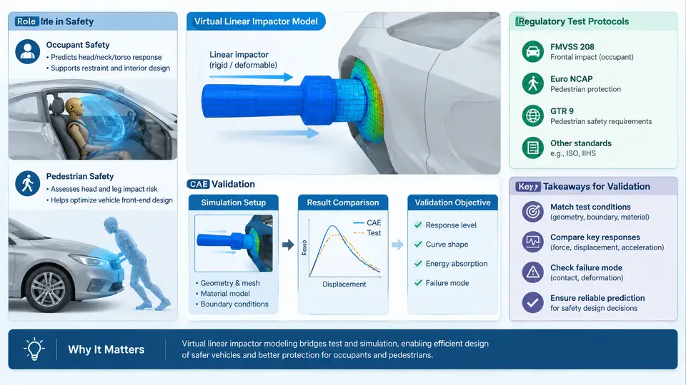
A virtual linear impactor is a CAE representation of the physical linear impactor used in occupant and pedestrian protection testing. Instead of firing a rigid or deformable striker at a stationary target in a laboratory, the virtual model reproduces the same event inside an explicit dynamics solver: the striker mass, the impactor face geometry, the initial velocity vector, the contact interface, and the response of the struck structure are all represented numerically. The purpose is not to replace the physical test, but to make the design space explorable long before hardware exists and to explain why a given test produced the result it did.
The linear impactor family covers several distinct devices. In occupant protection, the most familiar are the Hybrid III and THOR dummy subsystems used in sled and full-scale tests, and the free-motion headform (FMH) used in FMVSS 201U upper interior head impact. In pedestrian protection, the pedestrian headform (adult and child), the upper legform, and the lower legform are launched by a linear impulsion system against a vehicle front-end buck. Each device has a defined mass, geometry, and instrumentation set, and each is governed by a regulatory or consumer-rating protocol that fixes the impact conditions.
Why the linear impactor matters in safety engineering
The linear impactor is attractive because it isolates a single load path. A full vehicle crash test couples the barrier, the body structure, the restraint system, and the occupant into one event. A linear impactor test, by contrast, holds the target structure fixed and delivers a controlled pulse to one region. That isolation makes the test both a regulatory compliance tool and a diagnostic instrument. When a headform strikes a B-pillar trim at 24 km/h and the resultant head acceleration exceeds the injury threshold, the engineer knows the problem is local to the trim, the pillar, or the interface between them — not the restraint tuning.
From a CAE perspective, the same isolation is what makes the virtual linear impactor a high-value model. It is small enough to run in minutes rather than hours, it is sensitive to material card choices and contact definitions, and it produces a small number of scalar outputs that map directly to pass/fail criteria. This combination makes it an ideal validation vehicle for the modeling practices that will be reused in larger, more expensive simulations.
Regulatory and consumer-rating protocols
The protocols that drive linear impactor modeling are explicit about the initial conditions, because the test must be repeatable across laboratories. The table below summarizes the conditions that a virtual model must reproduce for the most common cases.
| Protocol | Impactor | Mass | Impact speed | Primary metric |
|---|---|---|---|---|
| FMVSS 201U | Free-motion headform, 165 mm diameter | 4.54 kg | 24.1 km/h (15 mph) | HIC(d) ≤ 1000 |
| UN R127 (pedestrian) | Adult / child headform | 4.5 kg / 3.5 kg | 40 km/h / 35 km/h | HIC ≤ 1000 / 1700 |
| Euro NCAP pedestrian | Upper legform | 9.5 kg | 40 km/h | Bending moment, force sum |
| Euro NCAP pedestrian | Lower legform | 13.1 kg | 40 km/h | Tibia acceleration, knee shear |
Two conventions deserve emphasis because they are frequent sources of modeling error. First, the impactor is treated as a rigid body in most linear impactor models; the compliance of the striker face is either neglected or represented by a thin deformable layer. Second, the impact angle is defined relative to the vehicle surface normal, not the global vertical. A model that applies the velocity vector in the global frame without rotating it to the local surface normal will produce a plausible-looking but incorrect result.
CAE validation objectives
A virtual linear impactor model is validated against physical test data, and the validation has three distinct objectives that should not be conflated.
- Kinematic correlation. The impactor's velocity and displacement history must match the test within a stated tolerance. This is the easiest objective to satisfy and the least informative.
- Injury-metric correlation. The predicted HIC, bending moment, or acceleration peak must fall within an acceptable band of the measured value. This is the objective that regulators and customers care about.
- Mechanism correlation. The model must reproduce the sequence of events — which component contacts first, when the trim separates, where the load path transitions. A model that matches the peak but gets the sequence wrong is not predictive.
The third objective is the one that distinguishes a validated model from a calibrated one. Calibration tunes parameters until the curve matches; validation demonstrates that the model responds correctly to conditions it was not tuned against. A practical test is to hold back one impact location or one speed from the calibration set and check the model's prediction there.
Modeling workflow and the role of the SVG
The figure below shows the data flow of a typical virtual linear impactor study, from the physical test that provides the reference through the model build, the correlation loop, and the final validated model that feeds design decisions. The key point is that the physical test is not a single checkpoint at the end — it supplies the initial conditions, the boundary conditions, and the correlation targets at different stages.
The loop on the left of the figure is where most of the engineering effort is spent. A first-pass model typically matches the impactor kinematics well but over- or under-predicts the peak force, because the target structure's stiffness is dominated by a small number of features — a rib, a clip, a foam density gradient — that are easy to idealize incorrectly. The refinement step is therefore not a matter of tuning a global scale factor; it is a matter of identifying which local feature controls the response and representing it more faithfully.
A minimal worked example
Consider a free-motion headform striking a B-pillar upper trim at 24.1 km/h. The physical test reports a peak resultant head acceleration of 145 g and a HIC(d) of 780. The initial virtual model uses a rigid headform, a shell-element trim with a linear elastic material, and a penalty contact with a friction coefficient of 0.3. The model predicts a peak of 190 g and a HIC(d) of 1120 — a clear fail.
The first diagnostic is the contact stiffness. A penalty contact that is too stiff produces a sharp, high-magnitude force spike. Reducing the penalty scale factor from 1.0 to 0.5 lowers the peak to 168 g but does not change the pulse shape, which indicates the problem is not the contact. The second diagnostic is the trim material. Replacing the linear elastic card with a piecewise linear plasticity card that includes the trim's actual yield stress and failure strain changes the pulse shape: the peak drops to 152 g and the HIC(d) to 840. The remaining gap is closed by adding the foam layer behind the trim, which absorbs the initial contact energy and delays the load transfer to the pillar. The final model predicts 148 g and HIC(d) 800, within 5% of the test.
The lesson is that the virtual linear impactor is sensitive to the sequence of energy absorption, not just the total. A model that gets the total energy right but distributes it incorrectly will match the peak and miss the pulse shape — and the pulse shape is what determines HIC.
What this chapter establishes
The virtual linear impactor is a small, fast, and highly diagnostic model that sits at the center of occupant and pedestrian safety CAE. Its value comes from isolation: one load path, one set of initial conditions, one set of scalar outputs. The validation objectives are kinematic, metric-based, and mechanistic, and only the third makes the model predictive. The remainder of this course builds the model in detail — geometry preparation, material characterization, contact definition, solver settings, and correlation practice — using the workflow and conventions introduced here as the reference frame.