3. SAB impact test setup
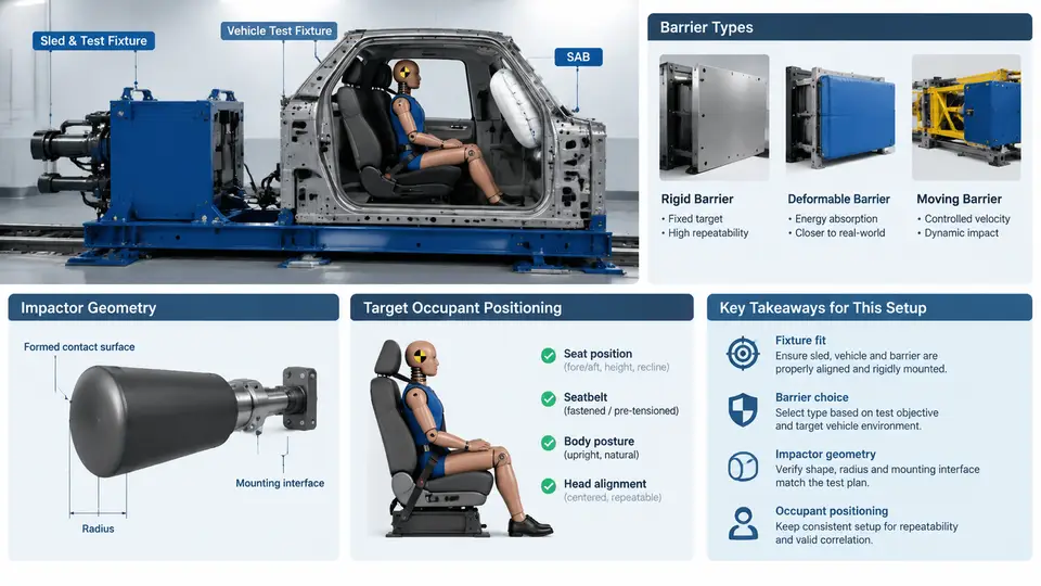
Side airbag (SAB) impact testing exists to answer one deceptively simple question: when the inflating bag meets a moving occupant, does the interaction protect the head, thorax, and pelvis without introducing new injury risk? Everything in the test setup — the fixture, the barrier, the impactor, and the occupant target position — exists to make that question answerable and repeatable. This chapter walks through the physical hardware and positioning conventions that define a valid SAB test, and explains how each choice propagates into the CAE correlation that follows.
Test Platforms: Sled Versus Vehicle
Two platforms dominate SAB development. The vehicle test uses a complete body-in-white or a full vehicle with the seat, trim, door, and airbag module installed exactly as in production. A moving deformable barrier (MDB) or a rigid moving barrier strikes the vehicle side at a prescribed speed and angle. Vehicle tests capture the true load path — door intrusion, B-pillar deformation, seat structure flex — but they are expensive, destructive, and slow to iterate.
The sled test isolates the occupant-and-airbag system. A body block or buck representing the door and seat is mounted on a deceleration sled, and the sled is accelerated or decelerated to reproduce the crash pulse measured in a vehicle test. The airbag module fires at a defined time-of-flight (TOF), and the occupant — usually an instrumented dummy — loads the bag. Sled tests are cheaper, highly repeatable, and ideal for parameter sweeps (TOF, bag pressure, vent size), but they omit structural intrusion unless the buck is designed to deform.
The practical rule: use the vehicle test to establish the reference pulse and intrusion profile, then build a sled buck that reproduces that pulse at the seat mounting points. If the sled pulse and the vehicle pulse diverge by more than roughly 10% in peak deceleration or 5 ms in duration, the correlation is compromised before the airbag is even considered.
Barrier Types and Their Purpose
Barrier selection defines the loading mechanism. The most common configurations are:
- Moving Deformable Barrier (MDB) — a trolley carrying a deformable honeycomb face, used in FMVSS 214 and Euro NCAP side impact. The honeycomb crush simulates a striking vehicle's front end. Its mass and face stiffness are fixed by regulation, so it is the standard for regulatory side impact.
- Rigid moving barrier — a non-deforming face used when the goal is a controlled, repeatable intrusion rather than a realistic vehicle-to-vehicle load. Common in component-level sled work.
- Pole / rigid column — a fixed cylindrical obstacle used in pole side impact tests (e.g., FMVSS 201U, Euro NCAP pole). The pole concentrates load over a narrow contact patch, which is the worst case for head and thorax.
- Interior impactor — a free-motion headform or body block launched at a stationary vehicle or trim buck, used for FMVSS 201 interior head impact and for SAB deployment-out-of-position (OOP) checks.
Each barrier imposes a different contact geometry and rate. A pole test drives the head toward the bag along a near-radial path; an MDB test produces a broader, lower-rate intrusion. The CAE model must reproduce the barrier's face stiffness and mass, not just its shape, or the intrusion pulse will be wrong.
Impactor Geometry
When the test uses a free-flying impactor rather than a full barrier, geometry becomes the dominant variable. The headform is a 4.54 kg sphere with a 165 mm diameter, instrumented with a triaxial accelerometer at its center of gravity. The thorax impactor is a 23.4 kg cylinder with a 305 mm diameter face, used for side interior impact. For SAB OOP testing, a small female or 5th percentile headform is often specified to represent the most vulnerable occupant.
Impactor geometry matters because the bag's deployment trajectory is not symmetric. A spherical headform approaching along the bag's deployment axis sees a different membrane tension than one approaching laterally. The contact patch area, the local bag curvature, and the vent flow all change with impactor shape. In CAE, the impactor must be modeled as a rigid body with the correct mass and inertia tensor; a point mass will not reproduce the rotational response that drives head angular acceleration.
Target Occupant Positioning
Occupant position is the single most sensitive variable in SAB testing. The dummy must be placed so that the head, thorax, and pelvis are in the positions defined by the test protocol — typically the H-point and torso angle are set first, then the head is positioned relative to the seat head restraint.
For in-position (IP) tests, the dummy sits in the normal seating posture: H-point at the design location, torso angle at 25° from vertical (or as specified), head centered on the head restraint. The airbag deploys into the gap between the dummy and the door, and the dummy loads the bag as the door intrudes.
For out-of-position (OOP) tests, the dummy is deliberately placed in a worst-case posture — head leaned toward the door, thorax rotated, or head resting on the door trim. The airbag then deploys directly into the occupant, and the test measures whether the deployment force itself causes injury. OOP positioning is defined by the test standard (e.g., FMVSS 208 side OOP, or the OEM's internal protocol) and must be reproduced exactly in CAE, including the dummy's joint angles and the initial gap to the trim.
The positioning sequence in practice is:
- Set the seat to the design H-point and torso angle using the H-point machine or a coordinate measuring arm.
- Place the dummy and adjust the pelvis, thorax, and head to the target coordinates within ±5 mm.
- Record the head-to-trim gap, the thorax-to-door gap, and the head-to-bag deployment axis angle.
- Verify the airbag module's TOF and the sled pulse against the reference.
In CAE, the same coordinates are applied to the dummy model's initial position. A common correlation failure is a mismatch in the head-to-trim gap: a 10 mm difference changes the time at which the head contacts the deploying bag, which shifts the peak head acceleration by 15–20%.
From Setup to Correlation
The setup choices above are not independent. Barrier type sets the intrusion pulse; the fixture determines how that pulse reaches the seat; impactor geometry defines the contact patch; and occupant position sets the initial gap and the deployment axis. In CAE correlation, each of these must be modeled explicitly. A common workflow is to first correlate the sled pulse alone (no airbag), then add the deploying bag with a rigid dummy, and finally introduce the deformable dummy and the door intrusion. If the head acceleration peak is off by more than 10% at the final stage, the error usually traces back to one of the four setup variables — most often the head-to-trim gap or the bag's TOF.
Documenting the setup in a test request form is therefore not paperwork; it is the correlation contract. The form should record the barrier type and mass, the sled pulse parameters, the impactor mass and geometry, the dummy H-point and torso angle, the head-to-trim and thorax-to-door gaps, the airbag TOF, and the ambient temperature. Any deviation from the reference setup must be logged, because a 5 mm positioning error or a 2 ms TOF shift will appear in the CAE comparison as an unexplained model error.
With the physical setup defined and documented, the next step is to translate it into a CAE model: mesh the barrier, assign the correct mass and inertia, apply the measured pulse, and position the dummy at the recorded coordinates. The quality of that translation determines whether the correlation is a validation of the airbag design or merely a validation of the analyst's assumptions.