1. SAB system fundamentals
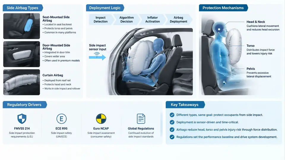
A Side Airbag (SAB) is a pyrotechnic or hybrid inflatable restraint mounted in the seat back, door trim, or roof rail, designed to mitigate thoracic, abdominal, and pelvic injury during lateral impacts. Unlike frontal airbags, which have a relatively generous crash pulse and a large occupant-to-instrument-panel gap, SAB systems operate in a compressed time and space envelope: the struck-side occupant can be only 150–250 mm from the intruding door trim, and the entire deployment must complete within roughly 20–30 ms. This tight timing budget is the single most important constraint that shapes every downstream decision in SAB design, testing, and CAE correlation.
Side Airbag Types and Their Packaging Envelope
Three mainstream SAB architectures dominate passenger-vehicle applications, and each imposes different boundary conditions on the impact test and the correlated CAE model.
- Thorax-only SAB (tSAB): A single-chamber bag of roughly 8–15 L, mounted in the outboard side of the seat back. It protects the rib cage and internal organs but leaves the pelvis and head uncovered. Deployment pressure typically peaks around 200–300 kPa.
- Thorax + pelvis SAB (tSAB + pSAB): A dual-chamber or single-chamber-with-partition design of 12–20 L. The pelvis chamber is usually inflated first or at higher pressure to react against the door trim and stabilize the occupant's lower torso.
- Combined curtain + thorax (CAB + tSAB): A roof-rail curtain airbag (15–30 L) covers the head and upper torso for rollover and far-side events, while a separate seat-mounted tSAB handles the thorax. This is the most common configuration in modern vehicles with side-impact and rollover regulatory obligations.
Packaging is the first engineering trade-off. A seat-mounted tSAB must fit inside the seat back foam without degrading comfort or lumbar support, which limits the folded bag thickness to roughly 25–40 mm. A roof-rail CAB must route along the A-, B-, and C-pillars and deploy downward through the headliner, which constrains the inflator position and the gas-flow path. These packaging constraints directly determine the initial conditions used in the CAE model: folded geometry, inflator mass flow rate, and vent-hole area.
Deployment Logic and Sensing Chain
SAB deployment is governed by a side-impact sensing chain that is physically and electrically separate from the frontal airbag chain. The typical signal path is:
- Satellite accelerometers or pressure sensors mounted in the B-pillar, door cavity, or seat frame detect the lateral crash pulse.
- The Airbag Control Unit (ACU) applies a crash algorithm that compares the integrated acceleration or pressure rise against a calibrated threshold within a 5–15 ms window.
- Deployment decision is issued to the SAB inflator, which is typically a hybrid inflator using compressed argon/helium plus a small pyrotechnic charge.
- Inflator output delivers 1.5–3.0 mol of gas in 10–20 ms, inflating the bag to its working pressure.
The critical calibration parameter is the deployment threshold, expressed as a function of lateral delta-v and crash severity. A threshold set too low causes unnecessary deployments in low-speed parking impacts; too high causes late or missed deployments in severe pole impacts. The ACU also applies a suppression logic based on occupant detection: if the seat is unoccupied or the occupant is out of position (OOP), the SAB may be suppressed or deployed at reduced pressure.
Occupant Protection Mechanisms
The SAB protects the occupant through three sequential mechanisms, each of which must be captured in the CAE correlation.
1. Load distribution. The inflated bag spreads the concentrated door-trim intrusion force over a larger contact area on the thorax, reducing peak rib deflection. A well-designed tSAB can reduce chest deflection by 20–35% compared to a no-airbag baseline in a 32 km/h MDB test.
2. Occupant kinematics control. The bag reacts against the door trim and the seat structure, creating a load path that decelerates the occupant's torso earlier and more uniformly. This reduces the relative velocity between the occupant and the intruding door, which is the primary driver of thoracic injury.
3. Pressure management. Vent holes and fabric permeability control the internal pressure decay after peak inflation. A bag that holds pressure too long becomes too stiff and increases injury risk; one that vents too quickly loses the load-distribution benefit. The vent area is typically 200–600 mm² per chamber, tuned to the specific crash pulse.
Regulatory and Rating Drivers
SAB design is driven by a combination of regulation and consumer rating programs, each with distinct test conditions and injury criteria.
| Driver | Test Condition | Key Injury Criterion |
|---|---|---|
| FMVSS 214 (US) | 27° crabbed MDB, 54 km/h | Thoracic Trauma Index (TTI) ≤ 85 (4-door) |
| UN R95 (EU) | MDB, 50 km/h | Rib deflection, abdominal force, pelvic force |
| Euro NCAP side impact | MDB, 60 km/h + pole, 32 km/h | Rib deflection, chest compression |
| IIHS side impact | MDB, 60 km/h, 1,500 kg barrier | Thoracic and pelvic injury measures |
The pole test is particularly demanding for SAB systems because the intrusion is localized and the occupant-to-door gap is small. A tSAB that performs well in the MDB test may still fail the pole test if the bag does not deploy fast enough or if the venting is too aggressive. This is why many OEMs now specify a dual-stage inflator that can adjust output based on crash severity and occupant position.
From System Fundamentals to CAE Correlation
Every element described above—bag geometry, inflator mass flow, vent area, deployment timing, and occupant position—becomes an input or a calibration target in the CAE model. The correlation task is to ensure that the simulated bag pressure, occupant kinematics, and injury metrics match the physical test within an acceptable tolerance. A typical acceptance criterion is a peak chest deflection correlation within ±10% and a deployment timing correlation within ±2 ms.
The diagram above summarizes the complete SAB system chain: the sensing and decision path at the bottom, the physical deployment and occupant interaction in the center, and the timing and protection mechanisms on the right. In the chapters that follow, each of these elements will be decomposed into its test and CAE correlation requirements—starting with the physical impact test setup and the instrumentation needed to capture the data that the CAE model must reproduce.