3. Impact test facility setup
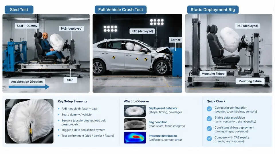
Passenger airbag (PAB) performance cannot be validated by a single test type. The PAB system must deploy reliably, at the right time, with the right pressure, and interact correctly with a restrained or out-of-position occupant. Three complementary facility configurations are used across the development cycle: the static deployment rig, the sled test, and the full vehicle crash test. Each answers a different question, and each imposes different constraints on instrumentation, fixture design, and correlation with CAE.
Static Deployment Rig: Free-Field and In-Vehicle Module Tests
The static deployment rig isolates the airbag module from vehicle dynamics. Its purpose is to characterize the inflator and cushion as a system: deployment timing, cushion pressure, seam integrity, and — critically for PAB — the interaction with the instrument panel (IP) tear seam and the windshield.
Two sub-configurations are common:
- Free-field (open-air) deployment: the module is mounted on a rigid fixture with no IP or windshield. This gives the baseline cushion fill curve and is used for inflator lot acceptance and CAE material-model calibration.
- In-vehicle-position static deployment: the module is installed in a production or representative IP, with the windshield and A-pillar trim present. This captures tear-seam opening, cushion trajectory over the IP top surface, and windshield contact.
A typical static rig setup uses a rigid steel frame anchored to a seismic mass. The module is bolted through its production mounting points with the production torque specification (for example, 8–10 N·m for M6 fasteners). The IP is supported so that its stiffness approximates the body-in-white (BIW) condition; a common mistake is to over-constrain the IP, which suppresses tear-seam opening and produces an unrealistically clean deployment.
Instrumentation for a static test usually includes:
- At least two pressure transducers inside the cushion (vent-side and throat-side) sampled at ≥ 20 kHz.
- High-speed video at 1000–2000 fps, with a calibrated grid in the field of view.
- A current probe on the inflator squib to record the fire command and confirm the trigger time.
- Optionally, a load cell under the module mount to capture reaction force.
The key output is the cushion pressure–time curve. For a 60 L class PAB at 23 °C, a representative curve rises to a first peak within roughly 15–25 ms of the fire command, then settles. If the first peak is late or low, suspect a restricted tear seam or a cold inflator. If the pressure spikes abnormally high, suspect a blocked vent or a cushion that failed to unfold.
Sled Test: Occupant Kinematics with Controlled Pulse
The sled test reproduces the crash pulse without destroying a full vehicle. It is the workhorse for PAB restraint-system tuning because it allows repeatable pulse control and dense instrumentation at lower cost than a full vehicle test.
The sled facility consists of a rail-mounted carriage, a propulsion system (typically a hydraulic or pneumatic accelerator, or a deceleration sled with a crushable or hydraulic absorber), and a body buck. For PAB work, the buck must reproduce the relevant BIW stiffness at the IP, toe board, and seat mounts. A common approach is to cut a section of the production BIW — the cowl, IP mounting structure, and floor pan — and weld it into the sled buck.
Pulse selection is the first engineering decision. For a frontal PAB evaluation, a typical pulse is a 50 km/h equivalent barrier pulse with a peak deceleration of about 35–40 g and a duration of 100–120 ms. The pulse is defined as a target corridor; the sled must stay inside the corridor at every time step. The corridor is usually specified as a band around a nominal curve, for example ±3 g or ±10% of the nominal value, whichever is greater.
Occupant setup follows the relevant regulation or internal standard. For a 50th percentile male Hybrid III, the seat is set to the mid-track position, the seat back angle to 25° from vertical, and the H-point located per the standard procedure. The PAB is fired at a time offset relative to the pulse onset — typically 10–20 ms after the pulse reaches its threshold — so that the cushion is fully inflated as the occupant moves forward.
Instrumentation on a PAB sled test typically includes:
| Channel | Sensor | Typical Sample Rate | Purpose |
|---|---|---|---|
| Sled acceleration | Accelerometer on carriage | 10 kHz | Pulse verification |
| Occupant head acceleration | Tri-axial accelerometer in head | 10 kHz | HIC calculation |
| Chest deflection | Chest potentiometer / IR-TRACC | 10 kHz | Chest compression |
| Cushion pressure | Pressure transducer | 20 kHz | Deployment timing |
| Fire command | Current probe | 20 kHz | Trigger reference |
After the test, the primary correlation metrics are head resultant acceleration, HIC15, chest deflection, and the time of head-to-cushion contact. The last is obtained from high-speed video and is the most sensitive indicator of deployment timing error. If the head contacts the cushion before it is fully pressurized, HIC rises sharply; if contact occurs after the cushion has begun to vent, the restraint effect is reduced.
Full Vehicle Crash Test: The Final Integration Check
The full vehicle test is the definitive validation. It uses a complete vehicle with production IP, windshield, seats, restraints, and all trim. The test can be a rigid barrier impact at 50 km/h (or the applicable regulatory speed), an offset deformable barrier (ODB) impact, or a pole test depending on the requirement.
For PAB evaluation, the critical difference from the sled is that the vehicle structure deforms. The IP moves rearward and downward as the front end crushes, which changes the effective distance between the module and the occupant. This structural motion is difficult to reproduce on a sled and is a major source of sled-to-vehicle correlation error.
Vehicle instrumentation mirrors the sled, with additional channels for:
- Vehicle longitudinal and vertical acceleration at the B-pillar and tunnel.
- IP displacement relative to the occupant compartment (using a string potentiometer or optical tracking).
- Windshield strain or crack detection if the cushion interacts with the glass.
The fire time is controlled by the vehicle's airbag ECU, which uses crash sensors to discriminate the event. In a full vehicle test, the actual fire time is measured from the squib current and compared with the ECU's intended command. A delay of more than a few milliseconds between command and squib current indicates a wiring or connector issue.
Choosing the Right Configuration and Correlating with CAE
The three configurations form a progression. The static rig calibrates the inflator and cushion model. The sled validates occupant kinematics and restraint timing under a controlled pulse. The full vehicle test confirms that the integrated system works with real structural deformation.
For CAE correlation, each configuration maps to a different model scope:
- Static rig → inflator mass-flow and temperature model, cushion fabric permeability, and seam failure criteria.
- Sled → occupant positioning, seat belt interaction, and PAB firing time. The sled model uses a prescribed pulse, so structural deformation is not simulated.
- Full vehicle → full frontal crash model with BIW, IP, and occupant. This is the most expensive and the most sensitive to material and joint modeling.
The facility setup is not a one-time decision. As the design matures, the same PAB module moves from static rig to sled to full vehicle, and the CAE model is refined at each stage. The correlation engineer's job is to ensure that the model scope matches the test scope — using a full vehicle model to correlate a static rig test, or a static rig model to predict sled HIC, will produce misleading results and wasted iterations.