1. PAB system fundamentals
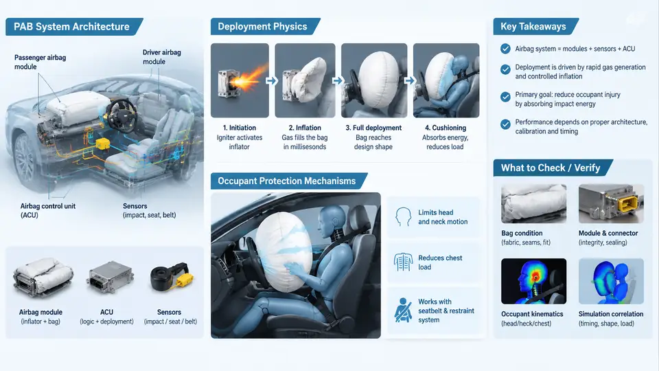
The Passenger Airbag (PAB) is a supplemental restraint system engineered to mitigate head and chest injuries for the front-seat occupant during a frontal collision. Unlike the driver airbag, which is packaged inside the steering wheel and deploys along a relatively short, well-controlled axis, the PAB must span a much larger and more variable space between the instrument panel (IP) and the occupant. This geometric reality drives nearly every design decision in the PAB subsystem — from module placement and chute routing to tether geometry and vent sizing. Understanding these fundamentals is a prerequisite for interpreting impact test results and for building a CAE model that correlates with physical behavior.
Module Architecture and Packaging
A typical PAB module consists of several tightly integrated subassemblies. The inflator — usually a hybrid or pyrotechnic gas generator — sits at the base of the module, mounted to a structural cross-car beam behind the IP. The cushion is folded in a controlled pattern and enclosed within a housing or canister. A chute (also called a deployment ramp or door flap) guides the cushion through the IP substrate and the visible tear seam on the A-surface. The module cover integrates with the IP skin and is designed to split along a hidden seam when the cushion pressure rises.
Packaging constraints are severe. The module must fit within the IP volume without intruding into the glovebox, HVAC ducts, or the cross-car beam. The deployment path must clear the windshield, the IP top surface, and any center stack trim. In many vehicles, the PAB is top-mounted (deploying upward through the IP top pad) or mid-mounted (deploying rearward through the IP face). The choice affects cushion trajectory, tear-seam location, and the risk of interference with the windshield or the occupant's head path.
Deployment Physics
Deployment is a rapid, staged process. Upon receiving a crash signal from the airbag control unit (ACU), the inflator initiates. In a hybrid inflator, a pyrotechnic initiator ignites a gas generant, and the resulting hot gas mixes with compressed inert gas (typically argon or helium) stored in a pressure vessel. The gas flows into the cushion through a diffuser, inflating it in tens of milliseconds.
The cushion must first break through the IP tear seam, then unfold and extend rearward toward the occupant. The unfolding sequence is critical: if the cushion contacts the occupant before it is fully extended, the occupant may be struck by a partially inflated cushion moving at high velocity — a condition known as "punch-out." Conversely, if deployment is too slow, the occupant may bottom out against the IP before the cushion provides restraint.
Key physical parameters include:
- Inflator output — mass flow rate and gas temperature, which determine cushion pressure and fill time.
- Cushion volume — typically 60–120 liters for a passenger airbag, depending on vehicle size and occupant packaging.
- Vent area — controlled leakage that allows the cushion to absorb energy rather than acting as a rigid balloon.
- Tether configuration — internal straps that shape the cushion and control its trajectory.
- Deployment angle — the vector along which the cushion exits the module, influenced by chute geometry and IP slope.
The interaction between inflator output and vent area determines the cushion pressure-time history. A typical PAB reaches peak pressure of 20–40 kPa (gauge) within 30–50 ms, then decays as gas vents through fabric porosity and explicit vent holes. This pressure profile is what the occupant actually feels; it must be tuned so that the cushion is firm enough to restrain the head and chest but compliant enough to avoid excessive rebound or neck loading.
Occupant Protection Mechanisms
The PAB protects the occupant through three primary mechanisms: energy absorption, load distribution, and kinematic control.
Energy absorption occurs as the occupant's head and chest compress the cushion. Gas is forced out through vents and fabric porosity, dissipating kinetic energy. The cushion acts as a nonlinear spring-damper: initially stiff as it resists compression, then softening as venting increases. The goal is to keep occupant deceleration within injury tolerance limits — typically expressed through HIC (Head Injury Criterion) and chest deflection metrics.
Load distribution spreads the restraint force over a larger area than a seat belt alone. The cushion contacts the head, face, and upper torso, reducing peak pressure on any single anatomical region. This is particularly important for the head, where concentrated loading can cause skull fracture or brain injury.
Kinematic control ensures the occupant's head and torso follow a controlled trajectory. The cushion's shape and tether configuration guide the head rearward and slightly upward, preventing it from sliding off the cushion or striking the IP or windshield pillar. This is especially critical for out-of-position (OOP) occupants, where the head may be close to the IP at deployment.
Key Design and Correlation Parameters
When correlating CAE with physical impact tests, several parameters must be matched carefully. The table below summarizes the most influential ones.
| Parameter | Typical Range / Value | Impact on Correlation |
|---|---|---|
| Inflator mass flow rate | 2–6 kg/s (peak) | Controls cushion fill time; mismatch shifts pressure peak timing. |
| Cushion volume | 60–120 L | Affects pressure decay and occupant contact stiffness. |
| Vent area | 2000–6000 mm² total | Primary tuning parameter for pressure-time curve. |
| Fabric permeability | 5–50 L/dm²/min | Secondary venting path; often overlooked in CAE. |
| Deployment angle | 15°–45° from horizontal | Determines cushion trajectory and IP clearance. |
| Tether length / position | Varies by geometry | Shapes cushion face; affects head contact location. |
Deployment Phases and Timing
The deployment process can be divided into four phases, each with distinct physical behavior and correlation challenges:
- Initiation (0–15 ms): The ACU sends a firing signal. The initiator ignites, and the gas generant begins burning. In CAE, this is modeled as a time-dependent mass flow inlet. The key correlation parameter is the delay between the electrical signal and the first gas entering the cushion.
- Inflation (15–40 ms): The cushion unfolds and extends. The tear seam opens, and the cushion emerges from the module. This phase is dominated by fabric unfolding dynamics and chute interaction. CAE models often use a simplified "uniform pressure" approach, but for accurate correlation, a coupled fluid-structure interaction (FSI) or corpuscular particle method (CPM) is preferred.
- Contact (40–70 ms): The cushion contacts the occupant. The occupant's head and chest begin to load the cushion. This is the most critical phase for injury metrics. Correlation requires accurate occupant positioning, seat belt status, and cushion pressure at contact.
- Ride-down (70–120 ms): The cushion vents gas as it absorbs occupant energy. The occupant decelerates. The pressure-time curve during this phase determines the rebound velocity and the final resting position of the occupant.
Out-of-Position (OOP) Considerations
OOP occupants — those positioned close to the IP at the time of deployment — represent a severe challenge for PAB design. If the occupant's head is within the deployment path, the cushion may strike the head before it is fully inflated, causing high local forces. To mitigate this, modern PAB systems use dual-stage inflators or adaptive venting. The ACU can detect occupant position via weight sensors, seat track position sensors, or interior cameras, and adjust the inflator output accordingly.
In CAE correlation for OOP, the occupant position must be precisely defined. A common test setup places a 3-year-old or 6-year-old child dummy (e.g., Hybrid III 3YO) close to the IP, with the head within 100–150 mm of the module cover. The CAE model must replicate this geometry exactly, including the dummy's posture and the seat position. The correlation metric is typically the head acceleration and neck force, compared against the physical test data.
Summary of Key Takeaways
- The PAB is a supplemental restraint that must span a large, variable space between the IP and the occupant.
- Deployment physics are governed by inflator output, cushion volume, vent area, and tether configuration.
- Occupant protection relies on energy absorption, load distribution, and kinematic control.
- CAE correlation requires accurate inflator mass flow data, cushion geometry, and occupant positioning.
- OOP scenarios demand adaptive deployment strategies and careful correlation of head/neck metrics.
With this foundation, subsequent chapters will build on the architecture and physics described here to develop detailed CAE modeling techniques, correlation methodologies, and validation criteria for PAB impact tests.