3. Airbag CAE in impact reconstruction
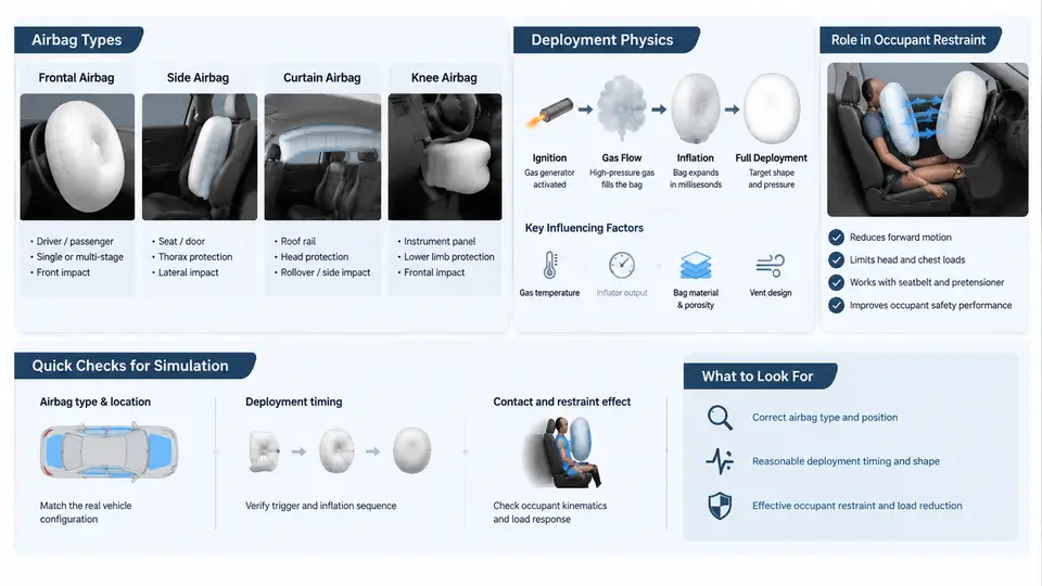
In a linear impact reconstruction, the airbag is not a decorative add-on to the occupant model — it is often the single component that decides whether the reconstructed injury outcome matches the field or test evidence. A belted Hybrid III dummy without a deploying airbag will load the chest through the belt and may show rib deflection that never occurred in the real event; conversely, an airbag that deploys too late or too weakly can leave the head uncaught and produce a head excursion that contradicts the physical evidence. This chapter explains which airbag types appear in reconstruction models, how their deployment is represented physically in CAE, and how they interact with the occupant restraint system during the impact event.
Airbag types encountered in reconstruction work
Reconstruction models rarely need the full OEM airbag catalogue, but they do need the correct class of inflatable restraint, because each class has a different fill law, vent behaviour, and interaction surface. The most common types are:
- Driver frontal airbag (DAB) — a single-chamber bag mounted in the steering wheel, typically 60–70 L, with two vent holes and a fabric permeability that controls pressure decay after peak.
- Passenger frontal airbag (PAB) — a larger, often dual-chamber bag (100–140 L) that must fill a wider space and is more sensitive to out-of-position (OOP) occupants.
- Side airbag (SAB) — a thorax or thorax-pelvis bag mounted in the seat, with a much smaller volume (12–20 L) and a very fast fill time, usually triggered by a side impact sensor.
- Curtain airbag (CAB) — a long, thin bag along the roof rail, modelled as a series of connected chambers to protect the head during rollover or side impact.
- Knee airbag (KAB) — a lower-mounted bag that controls femur and tibia loading, often paired with the DAB.
For reconstruction, the key question is not the part number but the fill curve (mass flow rate versus time), the vent area, and the bag geometry at full deployment. These three parameters dominate the occupant response.
Deployment physics in CAE
In a CAE model, an airbag is not simulated as a rigid expanding object. It is represented by a control-volume (CV) or corpuscular-particle (CP) method. The CV method solves the ideal-gas equation of state for the bag pressure:
P = (m R T) / V + P_atmwhere m is the mass of gas in the bag, R is the gas constant, T is the gas temperature, and V is the instantaneous bag volume. The solver integrates the mass flow from the inflator, subtracts the mass lost through vents and fabric leakage, and updates the pressure each time step. The bag surface is a membrane that expands against the occupant and the steering wheel or seat structure.
The CP method, by contrast, injects discrete gas particles that collide with the bag fabric and the occupant, giving a more detailed pressure distribution but at higher computational cost. For most reconstruction work, the CV method is sufficient and is the standard choice in LS-DYNA, PAM-CRASH, and Radioss.
Practical note: The inflator mass flow curve is usually supplied as a table of time versus mass flow rate (kg/s). If the OEM curve is unavailable, a generic curve scaled to the bag volume can be used, but the peak pressure and time-to-peak must be documented as assumptions in the reconstruction report.
Interaction with the occupant restraint system
The airbag does not act alone. Its effect is coupled to the seat belt, the seat structure, and the occupant kinematics. In a frontal reconstruction, the sequence is typically:
- 0–15 ms: Belt loads the pelvis and chest; the occupant begins to move forward.
- 15–30 ms: Inflator fires; bag begins to fill. The bag must reach the occupant before the head travels more than a few centimetres.
- 30–60 ms: Bag is fully inflated; head and chest contact the bag. The bag pressure peaks and then decays through vents.
- 60–120 ms: Occupant rebounds; belt and bag together control the rebound velocity.
If the bag is modelled with the wrong fill time, the head may pass through the deployment zone before the bag is pressurised — a condition known as bag slap or punch-out. In reconstruction, this shows up as an unrealistically high head acceleration or a head excursion that does not match the physical evidence.
Setting up an airbag in a reconstruction model
The following workflow is representative of a frontal reconstruction in LS-DYNA, but the logic applies to any explicit solver.
- Define the bag geometry. Use a reference mesh at full deployment. The mesh must be fine enough to capture contact with the head and chest; a 10–15 mm element size is typical for a DAB.
- Assign the CV or CP card. In LS-DYNA this is
*AIRBAG_HYBRIDor*AIRBAG_SIMPLE_PRESSURE_VOLUME. The card requires the inflator mass flow table, the vent hole area, and the fabric permeability. - Define the inflator curve. A typical DAB curve rises to 2–4 kg/s within 10–15 ms and then falls to zero by 40–50 ms. The exact shape must be documented.
- Set the vent area. A single vent hole of 20–30 mm diameter is common. The vent area controls the pressure decay after peak and therefore the rebound velocity.
- Couple to the occupant. Use a contact definition between the bag membrane and the dummy surface. The friction coefficient between fabric and dummy skin is typically 0.2–0.3.
- Run and inspect. Check the bag pressure history, the head acceleration, and the chest deflection. Compare the head contact time with the expected value from the reconstruction timeline.
Common failure: If the bag pressure never reaches a realistic peak (e.g., stays below 20 kPa), the inflator mass flow may be too low or the vent area too large. If the head passes through the bag without a clear contact force, the bag may be under-inflated at the moment of head arrival. Both symptoms indicate that the fill curve or the bag volume needs to be revisited.
What to document in the reconstruction report
Because airbag parameters are often estimated, the reconstruction report should state them explicitly. A minimal parameter table is shown below; it is an example of the level of detail expected, not a fixed template.
| Parameter | Example value | Source / assumption |
|---|---|---|
| Bag type | Driver frontal (DAB) | Vehicle inspection |
| Bag volume | 65 L | OEM data or measured |
| Inflator peak mass flow | 3.2 kg/s at 12 ms | Generic curve scaled to volume |
| Vent area | 2 × 25 mm diameter | Visual inspection |
| Fabric permeability | 5 L/dm²/min | Typical coated fabric |
| Time to full inflation | 28 ms | Simulation output |
The airbag is therefore both a physical object and a set of modelling assumptions. In reconstruction, the goal is not to reproduce the OEM calibration exactly, but to represent the deployment physics faithfully enough that the occupant response — head acceleration, chest deflection, and kinematics — is consistent with the evidence. When the airbag is modelled with the correct fill law, vent behaviour, and contact interaction, it becomes a reliable tool for testing alternative impact scenarios and for explaining the observed injury pattern.