1. Linear impact test reconstruction with a
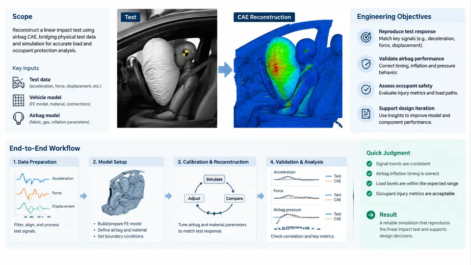
A linear impact test drives a sled along a straight rail and decelerates it with a programmable pulse, reproducing the occupant-level crash severity of a full-vehicle barrier event without destroying a body-in-white. When the restraint system includes an airbag, the sled alone cannot reproduce the occupant response: the bag must inflate, contact the occupant, and vent in the same time window as the physical test. Linear impact test reconstruction with airbag CAE is the discipline of building a simulation model that reproduces a specific physical sled test — same pulse, same occupant, same restraint hardware, same timing — and then using that validated model to explain what happened and to predict what will happen when a design variable changes.
This course treats reconstruction as an engineering deliverable, not as a software exercise. Across 30 chapters, you will move from test data intake through occupant/restraint modeling, airbag deployment and gas dynamics, contact and pulse correlation, and finally to documented model credibility and design-space exploration.
What "Reconstruction" Means in This Context
Reconstruction is distinct from two neighboring activities that are often confused with it:
- Prediction runs a model on a design that has not been tested. It requires a model whose credibility has already been established elsewhere.
- Correlation is the activity of adjusting a model until its output matches a reference. Reconstruction is the complete correlation package: it includes the reference data, the model, the objective comparison metrics, the documented deviations, and the engineering explanation for each deviation.
A reconstruction is complete when a reviewer can open the model, run it, reproduce the reported curves, and understand why the model differs from the test where it does. That last clause matters. A model that matches the peak chest acceleration to within 3% but has no physical justification for its airbag mass-flow curve is not a reconstruction — it is a curve fit that will fail the moment the pulse or the occupant size changes.
Engineering Objectives
Every reconstruction in this course is organized around four objectives, listed here in the order they constrain the modeling work:
- Reproduce the sled pulse. The input deceleration-time history must be applied to the model exactly as measured, including the sign convention and the integration method used to obtain velocity and displacement. A pulse that is filtered differently from the test data will shift the entire occupant response.
- Reproduce restraint timing. Airbag trigger time, time-to-first-gas (TTFG), bag fill, venting, and seatbelt load-limiter behavior must occur at the same instants as in the test. Timing errors of 5 ms are large enough to move the occupant forward into an uninflated bag.
- Reproduce occupant kinematics and injury metrics. Head and chest accelerations, head excursion, belt forces, and — where instrumented — chest deflection are the primary comparison channels. The target is not a single number but a curve shape over the full event window.
- Document credibility. Every material model, contact definition, and gas-property assumption must be traceable to a source: a coupon test, a component test, a supplier datasheet, or a stated engineering assumption.
End-to-End Workflow
The workflow below is the backbone of the course. Each stage produces a concrete artifact that the next stage consumes; skipping a stage usually shows up later as an unexplainable curve deviation.
Stage 1 — Test data intake and conditioning
Collect the sled pulse (accelerometer on the sled frame), the airbag trigger signal, belt force transducer data, and occupant accelerometer data. Confirm the sample rate, the anti-aliasing filter, and the sign convention. In this course we adopt the SAE J211 convention: positive X is forward (direction of travel), and the sled deceleration pulse is negative in X. All channels are filtered to CFC 60 for occupant accelerations and CFC 180 for the sled pulse unless the test report states otherwise. Resample all channels onto a common time base — typically 0.1 ms — before comparison.
Stage 2 — Model build
Build or import the sled buck, seat, belt, airbag, and occupant. The occupant is a validated ATD finite element model (Hybrid III 50th percentile male is the default in this course). The airbag is modeled with a control-volume or corpuscular-particle gas model; the choice depends on whether you need to capture bag-in-bag interaction and vent flow in detail.
Stage 3 — Airbag and gas dynamics setup
Define the inflator mass-flow rate and temperature history, the bag fabric permeability, the vent hole area, and the initial bag fold. These four inputs dominate the bag pressure-time curve, which in turn dominates the occupant's chest loading.
Stage 4 — Contact and pulse application
Define occupant-to-bag, occupant-to-belt, and occupant-to-seat contacts. Apply the measured sled pulse to the buck. Verify that the model's sled velocity and displacement match the test's integrated values before running the full occupant simulation.
Stage 5 — Correlation and iteration
Compare simulated and measured channels using objective metrics (peak value, time of peak, and a curve-shape metric such as CORA or a normalized integral difference). Adjust one parameter family at a time, and record every change.
Stage 6 — Documentation and design exploration
Freeze the correlated model, write the credibility report, and then run parametric studies — inflator output, vent area, trigger time, belt load limit — to answer the design question that motivated the reconstruction.
A Worked Example: Setting Up the First Correlation Run
Suppose a 50 km/h sled test with a 25 g, 90 ms pulse and a driver airbag triggered at 12 ms. Your first simulation run should not attempt to match everything. A practical sequence is:
- Run the model with the airbag disabled and the belt only. Compare belt force and chest acceleration. If the belt-only response is already 15% off, the occupant positioning or belt routing is wrong, and no amount of airbag tuning will fix it.
- Enable the airbag with the supplier's nominal inflator curve. Compare bag pressure at the in-bag pressure transducer location. A pressure curve that rises too slowly usually means the mass-flow rate is under-specified or the bag volume is too large.
- Compare head acceleration. A head that contacts the bag too early (before 30 ms) suggests the occupant is positioned too far forward or the trigger time is too late.
- Only after stages 1–3 are within reasonable agreement should you adjust vent area or permeability to fine-tune the chest loading.
What You Will Be Able to Do
By the end of this course, you should be able to take a physical linear impact test report, build a corresponding airbag CAE model, run the reconstruction, quantify the agreement channel by channel, explain the residual deviations in physical terms, and use the correlated model to evaluate at least one design change with a documented confidence statement. The remaining chapters build each of these capabilities in sequence, starting with the test data itself.