1. DAB system overview
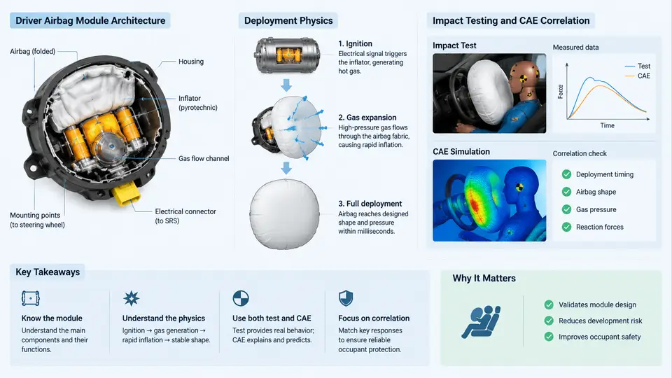
The Driver Airbag (DAB) is the primary restraint device for the vehicle occupant seated behind the steering wheel. Unlike a seat belt, which manages occupant energy through controlled webbing payout and load limiting, the DAB must deploy into the occupant's forward excursion path within tens of milliseconds and then absorb the remaining kinetic energy through venting and fabric compliance. Understanding how the module is built, how the inflator drives deployment, and how physical testing and CAE simulation are correlated is the foundation for every subsequent activity in this course — from sled setup to correlation metrics.
Module Architecture
A production DAB module is a self-contained subassembly mounted to the steering wheel armature. Its principal components are:
- Inflator — typically a pyrotechnic or hybrid gas generator. A hybrid inflator stores compressed gas (argon/helium) in a pressure vessel and augments it with a small pyrotechnic charge; a pure pyrotechnic inflator generates gas entirely from propellant combustion. The inflator defines the mass flow rate and gas temperature delivered to the cushion.
- Cushion (airbag) — a woven nylon 6.6 fabric, often silicone-coated on the inner surface to control permeability. The cushion geometry is defined by the folded pattern and the tether layout.
- Tethers — internal fabric straps that constrain cushion shape and depth. A typical DAB uses a central tether plus one or more radial tethers to control the deployed profile and prevent over-penetration toward the occupant.
- Vent holes — calibrated orifices in the cushion that release gas during occupant loading, providing the energy-absorption mechanism.
- Retainer ring and housing — a steel or aluminum ring that clamps the cushion to the module housing and reacts the deployment loads into the steering wheel structure.
- Cover — the visible steering wheel cover with a tear seam. The tear seam opens at a designed pressure threshold, and its opening behavior strongly influences early cushion trajectory.
The module is bolted to the steering wheel armature, which is itself mounted on the steering column. This means the DAB's reaction structure includes the column and its collapse mechanism, not just the wheel. Any correlation study must therefore treat the steering column as part of the boundary condition.
Deployment Physics
Deployment is a gas-dynamic and structural event that unfolds in roughly 30–50 ms from trigger to full cushion inflation. The sequence is:
- Trigger — the ECU fires the squib, igniting the initiator. Time zero (T0) is defined at the electrical trigger signal.
- Inflator output — gas generation begins within 1–2 ms. The inflator's pressure–time and mass-flow–time curves are the primary input to any deployment model.
- Cover opening — internal pressure rises until the tear seam ruptures, typically 5–15 ms after T0. The rupture pressure and the resulting flap geometry determine the initial cushion exit direction.
- Cushion unfolding — the folded cushion unfolds along its designed fold pattern. Fold sequence matters: an incorrect fold can cause the cushion to deploy laterally or downward instead of toward the occupant.
- Full inflation and venting — the cushion reaches full volume, then vents gas as the occupant loads it. The vent area and the cushion permeability govern the deceleration pulse delivered to the occupant.
The occupant's forward excursion is governed by the balance between the occupant's kinetic energy and the cushion's energy absorption. In a 50 km/h frontal barrier test, a 78 kg occupant (Hybrid III 50th percentile male) has approximately 7.5 kJ of kinetic energy at the moment of airbag contact. The cushion must absorb this over a stroke of roughly 150–250 mm, which implies an average restraint force on the order of 30–50 kN. This is why vent sizing and tether geometry are so sensitive: a small change in vent area shifts the force–deflection curve and can move occupant injury metrics by several percentage points.
Why Impact Testing and CAE Correlation Matter
Regulatory and consumer tests — FMVSS 208, ECE R94, Euro NCAP, C-NCAP — define the pass/fail criteria for occupant injury: HIC15, chest deflection, neck injury criteria (Nij), and femur loads. A DAB design must satisfy these criteria across a matrix of test conditions: different speeds, occupant sizes (5th percentile female through 95th percentile male), seating positions, and out-of-position (OOP) scenarios.
Physical testing is the ground truth, but it is expensive and slow. A single sled test can cost thousands of dollars and consume days of facility time. CAE simulation allows engineers to explore the design space — inflator output, vent area, tether length, fold pattern — before committing to hardware. However, a simulation is only useful if it is correlated: its predictions must match physical test results within an accepted tolerance.
Correlation is not a single number. It is a process of comparing time-history curves (cushion pressure, occupant head acceleration, chest deflection) and identifying where the model diverges. Common divergence sources include:
- Inflator modeling — using a simplified pressure–time curve instead of a mass-flow and temperature model.
- Fabric permeability — treating the cushion as impermeable or using a constant permeability instead of a pressure-dependent curve.
- Fold pattern — an idealized fold that does not match the production fold, causing different early deployment kinematics.
- Contact definition — incorrect friction or contact stiffness between cushion and occupant.
- Boundary conditions — a rigid steering column instead of a collapsible column model.
The correlation workflow typically proceeds in stages: first correlate the inflator alone (tank test), then the cushion deployment in free air (static deployment), then the full module in a sled test with the occupant. Each stage isolates a subset of physics, making it easier to identify the source of error.
From Architecture to Correlation: A Practical Example
Consider a hybrid inflator DAB for a mid-size sedan. The inflator's tank test produces a pressure–time curve peaking at 280 kPa at 25 ms. The cushion has a nominal volume of 65 L and two vent holes of 25 mm diameter each. In a 50 km/h sled test with a 50th percentile male, the measured head acceleration peaks at 72 g and HIC15 is 420.
A CAE model is built with the same inflator curve, a pressure-dependent permeability curve for the coated fabric, and a folded cushion geometry derived from the production fold. The first simulation predicts a head acceleration peak of 85 g and HIC15 of 560 — a 33% over-prediction. The engineer examines the cushion pressure history: the model shows a faster pressure rise than the test, suggesting the inflator mass flow is too high or the cushion volume is too small. After adjusting the inflator mass-flow curve to match the tank test more precisely and refining the fold pattern to match the production fold, the second simulation predicts 74 g and HIC15 of 445 — within 5% of the test. This is the correlation process in practice: iterative, physics-driven, and validated against measured data.
What This Course Covers
This course builds from the architecture and physics described here toward a complete correlation workflow. You will work with real test data formats, build and tune CAE models, apply correlation metrics, and diagnose common failure modes. The goal is not just to run simulations, but to know when a simulation is trustworthy and when it is not — and to understand the physical reasons behind every discrepancy.