3. CAB impact test setup
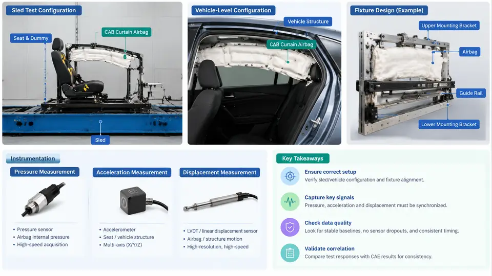
Curtain airbag (CAB) performance is validated through two complementary test platforms: the vehicle-level impact test, which reproduces the full body structure, trim, and occupant environment, and the sled test, which isolates the CAB and its mounting hardware on a controlled deceleration pulse. Understanding how each configuration is built, fixtured, and instrumented is essential before any CAE correlation can be trusted, because the correlation target is only as good as the physical measurement chain that produced it.
Vehicle-Level Configuration
In a vehicle-level test, the CAB is installed in the production body-in-white with the production headliner, A-pillar, B-pillar, C-pillar trim, grab handles, and roof rail attachments. This matters because the CAB deploys into a confined cavity bounded by trim panels; the trim stiffness, the gap between the airbag and the trim, and the presence of tether routing clips all influence the deployed shape and internal pressure history.
The most common vehicle-level CAB test is the side pole impact (FMVSS 201U / Euro NCAP oblique pole) and the moving deformable barrier (MDB) side impact. For a pole test, the vehicle is propelled laterally into a rigid pole at a defined velocity, typically 29 km/h for FMVSS 214 or 32 km/h for Euro NCAP, with the pole oriented at 75° or 90° to the vehicle longitudinal axis. The CAB must deploy and remain inflated long enough to cover the window opening during the occupant excursion.
Key setup parameters for a vehicle-level CAB test include:
- Impact velocity and angle — determines the lateral delta-v and the timing window for CAB deployment.
- Occupant positioning — the ES-2re or SID-IIs dummy is seated at the target seating position, with the head and torso positioned per the test protocol.
- Deployment trigger — the airbag ECU receives a signal from the side impact sensor; the time-zero (T0) is defined at the moment of pole contact, and the CAB must reach full inflation within 20–30 ms.
- Window opening coverage — the CAB must cover the entire window aperture from the A-pillar to the C-pillar and from the roof rail down to the beltline.
Sled Test Configuration
The sled test removes the vehicle body and replaces it with a rigid or semi-rigid fixture that holds the CAB, the roof rail, and the pillar trim in their production positions. The sled is accelerated or decelerated on a linear track to reproduce the lateral deceleration pulse measured in the vehicle test. This configuration is used for component-level validation, for parametric studies, and for CAE correlation because it eliminates body-structure variability and allows precise control of the pulse.
A typical CAB sled fixture consists of a steel frame that replicates the roof rail section, the A-pillar and C-pillar attachment points, and the window opening geometry. The fixture must be stiff enough that its own deformation does not contaminate the measurement; a common target is a first natural frequency above 100 Hz. The CAB is mounted using the production brackets and fasteners, and the trim panels are attached with production clips.
The sled pulse is defined as a deceleration-time history. For a side impact correlation, the pulse is often a half-sine or a trapezoidal pulse with a peak of 20–40 g and a duration of 50–80 ms. The pulse is measured with an accelerometer on the sled carriage and is used as the input boundary condition in the CAE model.
Time (ms)   Deceleration (g)
0           0
5           8
10          22
15          35
20          38
25          35
30          28
40          15
50          5
60 0Fixture Design Considerations
The fixture design directly affects the CAB deployment kinematics. Three factors are critical:
- Mounting point stiffness — the roof rail and pillar brackets must not flex under the airbag deployment force. If the fixture deflects, the CAB will deploy into a larger cavity than in the vehicle, reducing internal pressure and changing the head contact timing.
- Trim panel retention — the trim must be held with the same clip stiffness and gap as in the vehicle. A loose trim panel can be pushed out by the deploying airbag, which is a common source of correlation error.
- Window opening geometry — the fixture must reproduce the exact window aperture, including the beltline curvature and the pillar rake angles. A simplified rectangular opening will produce a non-representative deployed shape.
Instrumentation
Three measurement types are essential for CAB correlation: pressure, acceleration, and displacement.
Pressure measurement is performed with a pressure transducer mounted flush with the inner surface of the CAB cushion, or with a small tube routed into the cushion. The transducer must have a range of 0–300 kPa and a resonant frequency above 20 kHz to capture the rapid inflation transient. The pressure history reveals the inflator output, the cushion volume change, and any leakage through the seams or the fabric.
Acceleration measurement is performed with piezoelectric or piezoresistive accelerometers mounted on the sled carriage, on the fixture, and on the dummy head and chest. The sled carriage accelerometer defines the pulse input; the fixture accelerometers verify that the fixture is not resonating; the dummy accelerometers provide the injury criteria (HIC, rib deflection).
Displacement measurement is performed with a high-speed camera (1000–2000 fps) and with string potentiometers or laser displacement sensors. The camera tracks the CAB deployment front and the dummy head trajectory; the string potentiometer measures the CAB thickness at specific points. Displacement data is used to validate the CAE prediction of the deployed shape and the head-to-airbag contact timing.
Practical Setup Checklist and Common Pitfalls
When preparing a CAB impact test, the following items should be verified before the run. This checklist is written for a sled test but applies equally to vehicle-level testing with minor adjustments.
| Item | Check | Typical Failure Symptom |
|---|---|---|
| Fixture stiffness | Modal survey or tap test; fn > 100 Hz | High-frequency ringing in fixture accelerometer; CAB pressure spike |
| Trim gap | Feeler gauge at 3 points along roof rail | CAB deploys behind trim; trim panel ejected |
| Pressure transducer | Flush mount, no adhesive blockage | Pressure trace shows delayed rise or clipped peak |
| Accelerometer mounting | Torque per spec; cable strain relief | Noise floor elevated; signal dropout at T0 |
| Camera frame rate | ≥ 1000 fps; exposure < 100 µs | Motion blur on CAB front; unusable displacement data |
| T0 synchronization | Common trigger for DAQ and camera | Pressure and displacement traces offset by 1–2 ms |
| Pulse repeatability | Three consecutive runs within ±5% | Correlation scatter; non-physical CAE tuning |
From Measurement to Correlation
The instrumentation described above produces three primary signals: pressure–time, acceleration–time, and displacement–time. For CAE correlation, these are compared against the simulation outputs at the same physical locations. The pressure signal is the most sensitive indicator of inflator performance and cushion volume; the acceleration signal validates the structural boundary conditions; the displacement signal validates the deployment kinematics and the head contact timing.
A well-instrumented test will show a pressure rise from 0 to peak in 10–15 ms, a plateau during the inflation hold phase, and a decay as the gas cools and leaks. The acceleration pulse on the sled carriage should match the target pulse within ±5% in peak and duration. The displacement of the CAB front should reach the window opening centerline within 15–20 ms after T0. Any deviation from these expected ranges should be investigated before the data is used for correlation.
By keeping the fixture stiff, the trim retention representative, and the instrumentation synchronized, the test engineer ensures that the measured data reflects the CAB system behavior rather than the test rig. This is the foundation on which every subsequent CAE correlation is built.