1. CAB system fundamentals
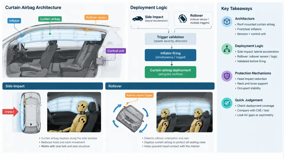
A Curtain Airbag (CAB) is a roof-rail-mounted inflatable restraint that deploys downward to cover the side glazing and upper side structure of a vehicle. Unlike a seat-mounted side airbag, which protects the thorax and pelvis, the CAB is primarily an upper-body and head protection device. Its coverage extends from the A-pillar to the C- or D-pillar, forming a cushion between the occupant's head and the side glass, B-pillar trim, and roof rail during side impact and rollover events. In the context of impact testing and CAE correlation, understanding CAB architecture and deployment logic is essential because the correlation target is not merely "did the bag inflate" but whether the bag's shape, pressure history, and coverage window match the physical test within acceptable tolerances.
1.1 Architectural Composition of a CAB System
A production CAB module consists of several interacting subsystems. The airbag cushion is typically a coated or uncoated woven nylon fabric (e.g., 470 dtex or 630 dtex) sewn into a single- or multi-chamber geometry. The inflator is usually a hybrid or pyrotechnic gas generator mounted at the roof rail, often near the B-pillar or C-pillar. The fill tube or internal tether distributes gas along the cushion length. The roof-rail mounting brackets and trim retention features control how the cushion breaks out of the headliner. Finally, the ECU and side-impact sensors (pressure sensors in the door cavity, accelerometers on the B-pillar or rocker) provide the crash signal that triggers deployment.
Two architectural variants dominate modern vehicles. A single-chamber CAB uses one continuous inflatable volume, which simplifies manufacturing but can produce uneven pressure distribution. A multi-chamber CAB divides the cushion into two or more cells connected by internal vents or tethers, allowing designers to tune pressure and stiffness independently for the front and rear seating positions. In CAE correlation, the chamber topology directly affects the predicted pressure-time curve and the contact force on the head, so the model must replicate the venting path and seam behavior.
1.2 Deployment Logic and Triggering Conditions
CAB deployment is governed by a discrimination algorithm in the airbag ECU. The ECU receives signals from side pressure sensors and/or accelerometers, filters them, and compares the result against a calibrated threshold. The key challenge is discrimination: the system must deploy for a severe side impact or rollover but not for a low-speed door slam, rough road input, or minor parking contact.
For side impact, the pressure sensor in the door cavity responds within a few milliseconds to the pressure rise caused by door intrusion. A typical calibration might require a pressure rise rate exceeding a threshold within a 5–15 ms window. For rollover, the ECU uses a roll-rate sensor and lateral accelerometer to detect a rotation angle and angular velocity consistent with a rollover event; deployment may occur before the vehicle reaches 90° of roll. The deployment time is typically 10–30 ms after the trigger decision, depending on inflator output and cushion volume.
In test and CAE correlation, the deployment logic is represented as a trigger time and a pressure-time curve applied to the cushion. The correlation engineer must verify that the CAE trigger time matches the test trigger time within a few milliseconds, and that the inflator mass flow rate produces a comparable pressure rise. A common error is to use a generic inflator curve instead of the actual tank test data for the specific inflator part number.
1.3 Occupant Protection Mechanisms
The CAB protects occupants through three primary mechanisms. First, head containment: the inflated cushion covers the side glass and upper pillar, preventing the head from contacting the glass or protruding objects. Second, energy absorption: the cushion vents gas through seams or vents, dissipating kinetic energy over a controlled stroke. Third, occupant kinematics control: the cushion interacts with the head and upper torso to reduce lateral excursion and prevent ejection through the side opening.
In a side impact, the occupant's head moves laterally toward the struck side. The CAB must be fully inflated before the head reaches the glass — typically within 20–30 ms. In a rollover, the occupant may move toward the side opening as the vehicle rotates; the CAB remains inflated for several seconds (typically 3–6 s) to provide continuous containment. This difference in inflation duration is a critical design and correlation parameter: a rollover CAB requires a larger inflator or a pressure-holding architecture, and the CAE model must simulate the long-duration pressure decay.
1.4 What This Means for Test and CAE Correlation
The correlation engineer must treat the CAB as a system, not just a bag. The physical test measures the cushion's pressure at one or more points, the head acceleration, and the deployment trajectory. The CAE model must reproduce these outputs by correctly representing the inflator mass flow, the cushion fabric permeability, the seam and vent behavior, and the interaction with the headliner and trim. A common practical workflow is to first correlate the free-deployment case (bag inflates into open air) to validate the inflator and cushion model, then correlate the blocked-deployment case (bag inflates against a rigid wall or headform) to validate the contact and pressure response, and finally correlate the full-vehicle side impact or rollover case.
For a side impact test, a typical setup uses a moving deformable barrier (MDB) or a pole impactor. The ES-2re or WorldSID dummy is seated in the struck-side position. The CAB must deploy and the dummy's head must not contact the glass or pillar. The correlation metric is often the head injury criterion (HIC) and the head excursion. In CAE, the same dummy model and barrier are used, and the CAB is represented by a finite element model with an inflator gas source. The correlation target is typically a 15% or 20% tolerance on peak head acceleration and a few millimeters on head excursion.
For rollover, the test may be a FMVSS 226 ejection mitigation test or a SAE J2114 dolly rollover. The CAB must remain inflated and contain the head within the side opening. The CAE model must simulate the long-duration pressure decay and the interaction with the dummy's head over several seconds. This is computationally more expensive and requires careful validation of the venting and leakage model.
1.5 Key Parameters for Correlation
| Parameter | Typical Value / Range | Correlation Impact |
|---|---|---|
| Inflator mass flow rate | 0.5–2.0 kg/s (peak) | Controls pressure rise time and peak pressure |
| Cushion volume | 20–40 L (single chamber) | Affects inflation time and pressure decay |
| Fabric permeability | 0.1–5.0 L/dm²/min | Determines gas leakage and long-duration pressure |
| Vent diameter | 10–30 mm | Tunes energy absorption and pressure decay |
| Trigger time | 5–15 ms after impact | Must match test within 2–3 ms |
| Deployment time to full inflation | 15–30 ms | Determines head containment timing |
| Rollover hold time | 3–6 s | Critical for ejection mitigation correlation |
These parameters are not independent. Increasing the inflator mass flow rate reduces inflation time but may increase peak pressure and head acceleration. Increasing vent diameter reduces peak pressure but may reduce the cushion's ability to contain the head. The correlation engineer must understand these trade-offs to diagnose mismatches. For example, if the CAE model predicts a faster pressure rise than the test, the inflator mass flow rate may be too high or the cushion volume too small. If the CAE model predicts a slower pressure decay, the fabric permeability or vent size may be underestimated.
1.6 Summary of the Correlation Workflow
The practical correlation workflow for a CAB system begins with a component-level validation: the inflator is tested in a tank, and the cushion is tested in a free-deployment setup. The CAE model is then tuned to match these results. Next, a subsystem-level validation is performed with a headform or dummy impacting the deployed cushion. Finally, the full-vehicle validation is conducted with the complete restraint system and the appropriate crash pulse. At each stage, the engineer compares pressure-time curves, head acceleration, and deployment trajectory. The goal is not a perfect match but a model that is predictive — one that can be used to evaluate design changes with confidence.
In the chapters that follow, we will apply this framework to specific test setups, CAE modeling techniques, and correlation metrics. The foundation established here — architecture, deployment logic, and protection mechanisms — is the reference against which all correlation results will be judged.