1. Airbag deployment physics and correlatio
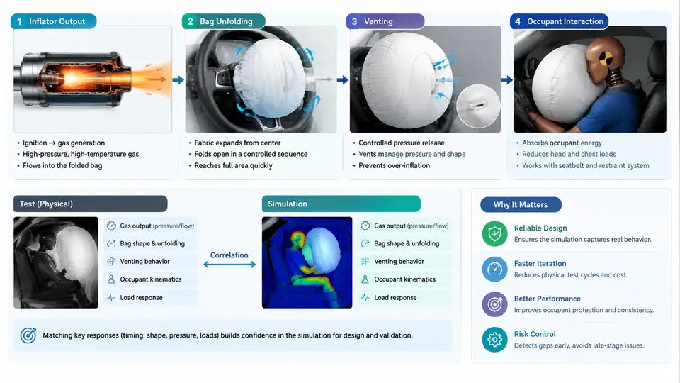
An airbag is not a single device but a short-lived thermodynamic and structural event. From the moment the crash sensor closes the loop to the instant the occupant rebounds into the seat, the restraint system passes through four tightly coupled physical stages: inflator output, bag unfolding, venting, and occupant interaction. Test–simulation correlation engineering exists because each stage is difficult to measure directly and expensive to iterate physically. The goal is not to make a model "look like" a test, but to make the model predict the same physical quantities that govern injury risk, within a known and defensible tolerance.
The Four Physical Stages
Inflator output. A pyrotechnic or hybrid inflator releases gas through a defined orifice area. The controlling quantities are mass flow rate ṁ(t), gas temperature, and the effective gas composition (often treated as a mixture with an equivalent specific heat ratio γ and gas constant R). The tank test is the canonical characterization method: the inflator fires into a fixed-volume tank, and the measured pressure rise is converted to mass flow using the ideal-gas relation
P(t)·V = m(t)·R·T(t)
ṁ(t) = (V / (R·T)) · dP/dt   (isothermal approximation)
ṁ(t) = (V / (γ·R·T)) · dP/dt (adiabatic approximation)
The choice of isothermal versus adiabatic treatment is itself a correlation decision. A 60 L tank fired at 23 °C with a 5 ms pressure rise will show a measurable difference between the two assumptions; the modeler must pick the convention that matches the downstream bag simulation.
Bag unfolding. The folded cushion is a constrained membrane. Deployment is driven by internal pressure acting on the fabric, resisted by fold friction, seam stiffness, and the inertia of the fabric itself. The key observable is the unfold trajectory: the time at which the bag contacts the occupant, the contact area, and the local pressure at the contact patch. In simulation this is typically handled with a control-volume (CV) gas model coupled to a finite-element (FE) fabric model, or with a fully coupled ALE/FSI approach. The CV approach is faster and is the workhorse for restraint system development; the ALE approach is reserved for detailed studies of fold behavior and seam loading.
Venting. Gas escapes through fabric porosity and through discrete vent holes. Venting controls the pressure–time history after peak inflation and therefore the "ride-down" phase. A bag that vents too slowly becomes a rigid surface; one that vents too quickly loses restraint. Vent area, fabric permeability, and vent location are the primary tuning parameters. In a model, venting is represented by a discharge coefficient Cd and an effective area Aeff:
ṁ_vent = C_d · A_eff · sqrt(2·ρ·(P_bag − P_amb))Occupant interaction. The occupant is not a rigid body. The chest, head, and abdomen have different stiffness and mass, and the interaction is a two-way coupling: the bag loads the occupant, and the occupant compresses the bag, raising its internal pressure. The output of interest is the injury metric — HIC, chest deflection, or Nij — computed from the occupant's acceleration and displacement history.
Why Correlation Is a Discipline, Not a Checkbox
A model that matches one test at one temperature and one inflator lot is not correlated; it is fitted. Correlation engineering requires that the model reproduce the physics across the operating envelope: inflator temperature (−35 °C to +85 °C), occupant size (5th percentile female to 95th percentile male), seat position, and out-of-position (OOP) scenarios. The practical workflow is:
- Characterize the inflator with tank tests at multiple temperatures. Fit ṁ(t) and T(t) to the measured pressure. Document the gas law assumption.
- Build the bag model from the folded geometry. Calibrate fabric permeability and seam stiffness against static pressure–volume tests where available.
- Run the sled or component test with the same inflator and bag. Record P(t) at the bag center and occupant kinematics.
- Compare simulated and measured P(t), unfold timing, and injury metrics. Adjust the dominant parameters — usually Cd, fold friction, and occupant stiffness — in that order.
- Validate on a held-out test condition not used for calibration. If the model fails there, the correlation is not yet robust.
| Quantity | Test source | Simulation output | Acceptance (example) |
|---|---|---|---|
| Peak bag pressure | Tank / sled P(t) | CV gas model | ±10 % of Pmax |
| Time to peak | High-speed video | Unfold solver | ±2 ms |
| Vent decay slope | P(t) after peak | Vent model | ±15 % of dP/dt |
| HIC | Sled accelerometer | Occupant model | ±15 % |
| Chest deflection | Deflection sensor | Occupant model | ±5 mm |
Common Failure Modes and Troubleshooting
When a model diverges from test, the symptom usually points to a specific stage. A bag that inflates too slowly in simulation but matches in test often indicates an over-stiff fold model or an underestimated ṁ(t) at low temperature. A bag that peaks too high and decays too slowly suggests Cd is too low or Aeff is underestimated. An occupant model that predicts lower HIC than test may have occupant stiffness set too high, or the bag may be contacting the occupant later in simulation than in reality. The diagnostic order should follow the energy path: inflator → bag → vent → occupant. Do not tune the occupant model to compensate for an inflator error; that produces a model that fails when the inflator lot changes.
What Correlation Engineering Delivers
The deliverable of a correlation project is not a single number but a validated model with a documented uncertainty budget. That model can then be used to evaluate design changes — a larger vent, a different fold, a softer inflator — without building a physical prototype for every iteration. In restraint system development, this is what compresses the design cycle from months to weeks. The model is trusted only within the envelope where it has been validated; outside that envelope, it is a hypothesis, not a prediction.
The next chapters will build on this foundation: inflator characterization in detail, bag folding and unfolding mechanics, venting and pressure management, occupant interaction modeling, and the statistical methods used to quantify correlation quality.