1. Airbag system architecture and deploymen
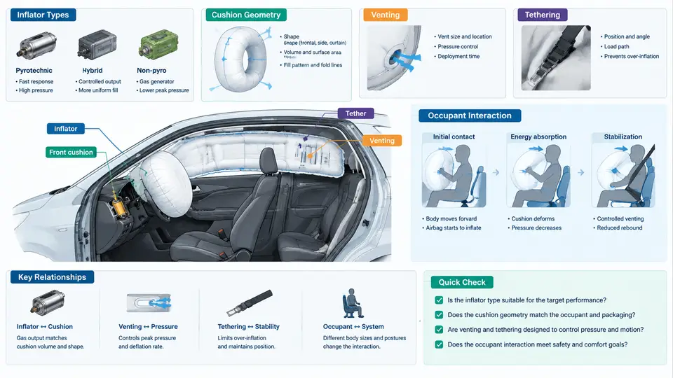
An airbag is not a single product but a tightly coupled energetic system. Its job is to convert stored chemical energy into a controlled gas volume within tens of milliseconds, then dissipate that volume before the occupant rebounds into the structure. Understanding validation and CAE sign-off begins with the architecture: what the inflator is, how the cushion is shaped, how gas escapes, how tethers constrain the bag, and how all of this interacts with a moving human body.
Inflator Types and Their Output Characteristics
Three inflator families dominate passenger-vehicle restraint systems, and each produces a distinctly different pressure–time signature.
- Pyrotechnic inflators burn a solid propellant (typically sodium azide–free formulations such as guanidine nitrate based) to generate gas directly. They are compact and fast, reaching peak pressure in roughly 20–40 ms, but their output is hot and chemically aggressive, requiring a filter and heat sink.
- Hybrid inflators combine a small pyrotechnic charge with a stored compressed gas (argon or helium mixture). The burning charge heats and releases the stored gas, giving a cooler, more controllable output. Hybrids are common in driver-side modules.
- Stored-gas inflators rely purely on a compressed gas reservoir released by a pyrotechnic initiator. They are the coolest option and are frequently used in side airbags and curtain systems where hot gas near the head is undesirable.
The key engineering parameter is the mass flow rate ṁ(t) and its integral, the total gas mass delivered. A typical driver inflator might deliver 60–120 g of gas over 30–50 ms. The tank pressure test (a fixed-volume vessel instrumented with a pressure transducer) is the standard bench method for characterizing this curve before any cushion is attached.
Cushion Geometry and Volume
Cushion geometry is defined by the folded envelope, the deployed shape, and the internal volume. Driver airbags are typically 60–70 L; passenger airbags range from 90–150 L depending on the instrument-panel packaging. The deployed shape is not arbitrary — it is tuned so the bag contacts the occupant's chest and head at the correct time and with the correct surface angle.
Two geometric parameters matter most during validation:
- Stand-off distance — the gap between the module and the occupant's nominal position. Too small and the bag strikes the occupant while still deploying (high risk of injury); too large and the occupant has already moved forward before the bag is fully inflated.
- Contact area — the projected area of the bag that meets the occupant. A larger, flatter contact area distributes force and reduces peak pressure on the body.
Venting: The Pressure Relief Mechanism
Without venting, an airbag would behave like a rigid balloon and cause injury. Vents are engineered openings — either sewn fabric gaps, die-cut holes, or one-way valves — that allow gas to escape as the occupant compresses the bag. Vent area is one of the most sensitive tuning parameters in the entire system.
The governing relationship is a balance between inflow and outflow. During the inflation phase, inflator mass flow dominates and the bag pressurizes. During the interaction phase, the occupant's motion displaces gas, and the vent area determines how quickly pressure decays. A useful first-order model treats the bag as a control volume:
dP/dt = (γ·R·T / V) · (ṁ_in − ṁ_out) − (γ·P / V) · dV/dt

where:
  P      = bag gauge pressure
  V      = instantaneous bag volume
  γ      = ratio of specific heats (~1.4 for air-like gas)
  R      = specific gas constant
  T      = gas temperature
  ṁ_in   = inflator mass flow rate
  ṁ_out  = vent mass flow rate (function of P and vent area)
  dV/dt  = volume change rate from occupant penetration
In practice, vent sizing is validated with a static deployment test using a calibrated impactor (a rigid or deformable headform/chestform) that penetrates the bag at a controlled velocity. The measured bag pressure and impactor deceleration are compared against the CAE prediction.
Tethering and Shape Control
Tethers are internal fabric straps that limit how far the cushion can expand in specific directions. They serve three purposes: controlling the deployed depth (so the bag does not over-extend into the occupant), shaping the bag to match the occupant's anatomy, and preventing the bag from wrapping around the A-pillar or steering wheel rim.
A common configuration uses a horizontal tether across the bag's center to create a flatter, more uniform contact face. The tether length directly sets the maximum bag depth. During CAE correlation, tether length and attachment point coordinates are among the first parameters to be adjusted when the predicted bag shape deviates from the high-speed video of a physical deployment.
Occupant Interaction Mechanisms
The occupant does not simply "hit" the bag. The interaction is a coupled sequence:
- Deployment phase (0–30 ms): The bag unfolds and pressurizes. The occupant is still moving forward due to crash deceleration but has not yet contacted the bag.
- Contact phase (30–60 ms): The occupant's chest and head contact the bag surface. Bag pressure rises sharply as volume is compressed.
- Ride-down phase (60–120 ms): The occupant decelerates as gas vents through the openings. The bag acts as a damper, converting kinetic energy into gas flow and heat.
- Rebound phase (>120 ms): The bag has largely deflated; the occupant may rebound slightly. Residual pressure must be low enough to avoid pushing the occupant back into the seat.
The critical validation metric is the occupant's chest deceleration and head injury criterion (HIC), both of which are directly influenced by vent area, tether length, and inflator output. A bag that is too stiff (insufficient venting) produces high deceleration; a bag that is too soft (excessive venting) allows the occupant to bottom out against the steering wheel or instrument panel.
System-Level Architecture
Figure 1 shows the functional architecture of a typical driver-side airbag system, from crash sensor input through inflator firing to occupant interaction. The diagram highlights the key physical domains — sensing, actuation, gas dynamics, and occupant mechanics — and the feedback paths that validation engineers must correlate.
What This Means for Validation and CAE Sign-Off
Every physical test and every CAE model must resolve the same four domains shown above. A static deployment test validates the inflator and cushion geometry. A dynamic sled test validates the occupant interaction. A full-scale barrier test validates the complete system timing. CAE sign-off requires that the model reproduce the bag pressure curve, the deployed shape, and the occupant injury metrics within agreed tolerances — typically ±10% on peak pressure and ±15% on HIC.
The most common correlation failures trace back to three root causes: incorrect inflator mass flow input (often from using a generic tank curve instead of the actual inflator), unmodeled tether stretch or fabric permeability, and vent area that changes with bag pressure due to fabric deformation. Each of these is a physical mechanism that must be represented explicitly in the model, not lumped into a single tuning factor.
With the architecture and physics established, subsequent chapters will address how each subsystem is tested, how the CAE model is built and correlated, and what evidence is required for formal sign-off.