3. Airbag module and system-level test arti
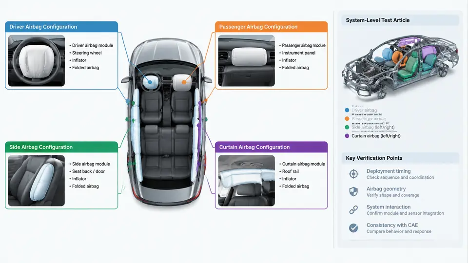
Pendulum impact testing does not begin with a bare inflator or a loose cushion. It begins with a defined test article — the physical assembly mounted on the fixture, complete with its module housing, trim, mounting brackets, and, where relevant, the surrounding body structure. The choice of test article determines what the pendulum actually measures. A driver-side module tested alone responds differently from the same inflator tested inside a full instrument panel with a steering column and a folded cushion constrained by a retainer ring. This chapter defines the four principal airbag configurations used in pendulum and CAE validation — driver, passenger, side, and curtain — and explains how each is prepared, fixtured, and instrumented so that the physical test and the simulation describe the same event.
Why the Test Article Definition Comes First
In a pendulum test, the impactor strikes the deployed or deploying airbag at a controlled velocity and mass. The measured quantities are typically impactor force, impactor displacement, and the pressure or acceleration inside the cushion. These quantities depend strongly on how the cushion is restrained. A driver airbag is anchored to a steering-wheel retainer; a passenger airbag is anchored to a module chute inside the instrument panel; a side airbag is anchored to a seat-back frame; a curtain airbag is anchored along the roof rail and A/B/C pillars. Each anchor path changes the effective stiffness and the reaction force the pendulum sees.
For CAE validation, the same logic applies. The finite element model must include the same boundary conditions as the physical fixture. If the physical test uses a rigid steering-column substitute but the CAE model uses a deformable column, the force–displacement curves will diverge even if the cushion model is correct. The test article definition is therefore the contract between physical test and simulation.
Driver Airbag Configuration
The driver airbag module consists of the inflator, the folded cushion, the retainer ring, and the module housing, mounted on the steering wheel. In a pendulum test, the steering wheel is usually replaced by a rigid fixture that reproduces the wheel rim geometry and the column angle. The module is bolted to the fixture at the same bolt pattern and torque as in the vehicle.
Typical preparation steps:
- Mount the module on the steering-wheel fixture at the design column angle (often 22°–25° from vertical for a driver airbag).
- Connect the inflator to the firing circuit and verify continuity.
- Position the pendulum so its face is centered on the module cover and at the specified standoff distance.
- Record the ambient temperature, since inflator output varies with temperature.
Instrumentation for a driver module usually includes a load cell in the pendulum face, a displacement transducer, and a pressure sensor threaded into the cushion. The key observable is the peak force and the time to peak. A common failure symptom is a force curve that rises too early — often caused by the cushion not fully deploying before impact, which points to a firing timing or inflator output issue rather than a cushion geometry issue.
Passenger Airbag Configuration
The passenger airbag is larger and is mounted inside the instrument panel, often with a chute that guides the cushion upward and rearward. The test article is typically the complete instrument panel section with the module installed, or a representative subassembly that preserves the chute geometry and the tear seam.
Because the passenger cushion is larger, the pendulum mass and velocity are usually higher than for a driver module. The standoff distance is also larger, and the impact point is offset from the module center to represent the occupant position. The tear seam is a critical feature: if it opens asymmetrically, the cushion deploys off-axis and the force curve shows a secondary peak. In CAE, the tear seam is modeled with a failure criterion, and the validation target is the opening time and the symmetry of the deployed cushion.
Side Airbag Configuration
Side airbags are mounted in the seat-back frame and deploy forward and outward. The test article is usually the seat frame with the module installed, mounted on a rigid fixture that reproduces the seat-back angle. The pendulum strikes the deployed cushion from the outboard side.
The critical parameters are the seat-back angle, the module mounting orientation, and the cushion deployment path. Because the side airbag is close to the occupant, the standoff is small and the pendulum velocity is lower than for frontal configurations. The force curve is typically sharper, and the peak force is more sensitive to the cushion fabric permeability. In CAE, the seat frame is often represented as a rigid body, but the cushion must be modeled with the correct fabric porosity to match the physical peak force.
Curtain Airbag Configuration
Curtain airbags are the most complex test article. They are anchored along the roof rail and extend from the A-pillar to the C-pillar, covering the side windows. The test article is typically a body-in-white section or a representative roof-rail and pillar structure with the curtain module installed.
The pendulum test for a curtain airbag usually targets a specific region, such as the front window or the rear window. The impactor is positioned to strike the deployed curtain at that region. The key observables are the cushion pressure, the deployment time, and the force at the impact point. Because the curtain is long and flexible, the force curve often shows a gradual rise followed by a plateau. A common failure symptom is a pressure drop during impact, which indicates a leak at a seam or a tether attachment point.
In CAE, the curtain model must include the tether lines and the attachment points. If the tethers are modeled as rigid links but the physical tethers stretch, the simulated cushion will be too stiff. The validation target is the pressure–time curve and the cushion shape at peak deployment.
Matching the Physical Test Article to the CAE Model
The most common source of discrepancy between pendulum test and CAE validation is a mismatch in the test article definition. Three checks should be performed before running either the physical test or the simulation:
- Mounting stiffness: The fixture or body structure that holds the module must have the same effective stiffness in both. A rigid CAE boundary condition against a flexible physical fixture will shift the force curve.
- Cushion restraint: The retainer ring, chute, or tether geometry must be identical. Small changes in the anchor point location change the cushion deployment path.
- Instrumentation location: The pressure sensor and load cell positions must match between physical and simulated setups. A pressure sensor placed near the inflator reads a different value than one placed near the cushion face.
Practical Example: Driver Module Pendulum Test Setup
Consider a driver airbag module with a 60 L cushion and a pyrotechnic inflator. The test article is mounted on a rigid steering-wheel fixture at a 24° column angle. The pendulum has a mass of 25 kg and strikes the deployed cushion at 6.0 m/s. The standoff distance is 150 mm from the module cover to the pendulum face.
Expected observable results (illustrative values, not measured data):
| Quantity | Expected Range | Notes |
|---|---|---|
| Peak force | 8–12 kN | Depends on cushion pressure and vent size |
| Time to peak | 25–40 ms | After firing signal |
| Peak cushion pressure | 180–250 kPa | At 23 °C ambient |
| Deployment time | 20–30 ms | Cover opening to full inflation |
If the measured peak force is significantly higher than the expected range, the first check is the vent hole size and the cushion permeability. If the time to peak is too early, the inflator output or the firing circuit timing should be reviewed. If the pressure drops sharply after peak, inspect the cushion seams and the retainer ring for leaks.
For CAE validation, the same setup is modeled with a rigid steering-wheel fixture, a folded cushion with the correct fabric properties, and a pressure sensor at the same location. The simulation is considered validated when the force–displacement curve and the pressure–time curve fall within the same range as the physical test, and the deployed cushion shape matches the high-speed video at the same time steps.
Summary
Driver, passenger, side, and curtain airbag configurations each require a distinct test article definition. The driver module is mounted on a steering-wheel fixture; the passenger module is tested with the instrument panel and chute; the side module is mounted on the seat frame; and the curtain module is anchored to the roof rail and pillars. In every case, the physical fixture, the cushion restraint, and the instrumentation must match the CAE model. The force–displacement curve, the pressure–time curve, and the deployed cushion shape are the primary validation targets, and any deviation should be traced back to a specific input — vent size, tear seam, tether, or mounting stiffness — rather than adjusted by trial and error.