1. Airbag pendulum impact testing
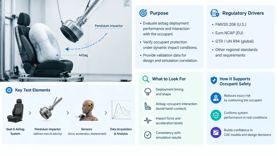
An airbag is a pyrotechnic restraint device that must deploy within tens of milliseconds and then absorb the occupant's kinetic energy without itself becoming a source of injury. Before any airbag module is released to a vehicle program, its deployment behavior and energy-absorption characteristics must be characterized under controlled, repeatable impact conditions. The pendulum impact test is the most fundamental of these characterization methods: a known mass, suspended on a rigid arm, swings into a statically mounted airbag module at a defined velocity, and the resulting force–time and pressure–time histories are recorded. Because the pendulum's kinetic energy is precisely calculable and the impact geometry is fixed, the test isolates the airbag's own mechanical response from the variability of a full vehicle crash.
This chapter establishes why pendulum testing exists, which regulatory and industry drivers require it, and how its results feed the broader occupant safety validation chain. Later chapters will cover the hardware, instrumentation, and CAE correlation workflow in detail; here the goal is to build the conceptual foundation that makes those details meaningful.
Why a Pendulum, and What It Actually Measures
A full frontal barrier crash test is the definitive occupant safety event, but it is expensive, destructive, and statistically noisy. A single sled or barrier test cannot tell an engineer whether a force spike came from the inflator's gas output, the fabric's seam strength, the venting strategy, or the module's mounting stiffness. The pendulum test decomposes the problem. By striking a static module with a known impactor, it converts a complex crash into a controlled materials-and-structure experiment.
The core measured quantities are:
- Impactor force — measured by a load cell in the pendulum face or arm, giving the reaction force the airbag exerts back on the striker.
- Internal bag pressure — measured by a pressure transducer mounted in the module or on the bag surface, revealing the inflation and venting timeline.
- Impactor displacement and velocity — from a string potentiometer, laser, or high-speed video tracking, used to compute absorbed energy.
- Deployment timing — the interval from initiator trigger to full bag pressurization, typically 20–50 ms for a driver-side module.
From force and displacement, the absorbed energy is obtained by numerical integration:
E_absorbed = ∫ F(x) dx   ≈ Σ F_i · Δx_i

where F_i is the instantaneous impactor force (N)
      Δx_i is the incremental displacement (m)
      E_absorbed is reported in joules (J)
A well-designed airbag absorbs the impactor's kinetic energy smoothly, with a force plateau rather than a sharp spike. A force spike indicates a "bottom-out" condition — the bag has compressed fully and the impactor is now loading the module structure or steering wheel armature directly. This is precisely the failure mode that pendulum testing is designed to expose before a vehicle ever reaches a barrier facility.
Regulatory and Industry Drivers
Pendulum testing is not an arbitrary internal practice; it is anchored in a hierarchy of requirements that span government regulation, industry standards, and OEM specifications.
| Driver | Document / Source | What It Requires |
|---|---|---|
| U.S. federal regulation | FMVSS 208 (Occupant Crash Protection) | Airbag deployment must not exceed occupant injury criteria; component-level validation supports the compliance demonstration. |
| European regulation | UN ECE R94 / R95 | Frontal and side impact protection; airbag performance is validated through sled and component tests. |
| Industry standard | SAE J2238 / ISO 12097 series | Defines airbag module test methods, including static deployment and impactor-based characterization. |
| OEM specification | Manufacturer-specific module validation plans | Prescribes pendulum mass, velocity, temperature conditioning, and pass/fail force and pressure envelopes. |
The regulatory logic is indirect but important to understand. FMVSS 208 does not literally say "perform a pendulum test." Instead, it sets occupant injury thresholds measured in a full barrier test with instrumented dummies. The pendulum test is an engineering enabler: it allows suppliers to demonstrate that a module will behave predictably across the production and environmental range, which is a prerequisite for the barrier test to pass reliably. In practice, OEMs translate the regulatory outcome into component-level specifications, and the pendulum becomes the contractual gate.
Where Pendulum Testing Sits in the Validation Chain
Occupant safety validation proceeds through a deliberate funnel, from cheapest and most controlled to most realistic and most expensive. Pendulum testing occupies the component tier, feeding both upward into system-level sled tests and sideways into CAE model correlation.
The funnel logic is straightforward. At the component tier, a pendulum test costs a fraction of a barrier test and can be repeated dozens of times to build statistical confidence. At the subsystem tier, a sled test adds the steering column, seat, and a dummy, capturing occupant kinematics but still without the full vehicle's structural deformation. At the full vehicle tier, the barrier test is the regulatory event, but it is too expensive and too variable to serve as a development tool. The pendulum test exists because it gives engineers a fast, repeatable, and physically interpretable signal that can be used to calibrate CAE models, which then predict the more complex events.
What a Pendulum Test Actually Looks Like in Practice
Consider a driver-side airbag module mounted on a rigid fixture that reproduces the steering wheel's mounting angle and stiffness. The pendulum arm is raised to a height that yields the specified impact velocity — for example, a 30 kg impactor at 6.0 m/s, corresponding to a kinetic energy of 540 J. The module is conditioned to a specified temperature (e.g., −35 °C, +23 °C, or +85 °C) to represent the environmental range the vehicle will see in service.
At trigger, the inflator fires and the bag begins to deploy. The impactor is released simultaneously or after a defined delay, depending on whether the test is a static deployment (bag inflates freely, then is struck) or a dynamic deployment (bag inflates while being struck). The distinction matters: static deployment characterizes the bag's fully inflated energy absorption, while dynamic deployment captures the interaction between the deploying bag and an occupant who is already moving forward.
Typical observable outcomes and their interpretation:
- Smooth force plateau — the bag is venting correctly and absorbing energy at a controlled rate. This is the desired result.
- Early force spike followed by a drop — the bag may be over-pressurized or the vent is too small; the spike represents a hard initial contact before venting begins.
- Late force spike near maximum displacement — bottom-out; the bag has insufficient volume or the impactor has reached the module structure. This is a fail condition.
- Pressure decay faster than expected — excessive venting or seam leakage; the bag cannot sustain the force plateau.
- Erratic or noisy force signal — often indicates fabric flutter, tether slap, or a loose mounting fixture. Check fixture torque and bag folding pattern.
How Pendulum Results Feed CAE Validation
The pendulum test is the primary calibration event for airbag CAE models. A typical workflow proceeds as follows:
- Run the physical pendulum test and record force–time, pressure–time, and displacement–time curves.
- Build a CAE model of the same setup: rigid impactor, airbag fabric with defined permeability, inflator mass-flow curve, and vent orifice.
- Simulate the impact and compare the predicted force and pressure curves against the test data.
- Adjust model parameters — fabric Young's modulus, permeability coefficient, inflator mass-flow rate, vent discharge coefficient — until the curves match within an agreed tolerance (commonly ±10% on peak force and ±5 ms on timing).
- Use the validated model to predict sled and barrier test outcomes, reducing the number of physical prototypes required.
The tolerance values above are representative of common industry practice and should be confirmed against the specific OEM or supplier specification governing a given program. The key point is that the pendulum test is not an end in itself; it is the anchor point that makes the entire CAE validation chain credible. Without a well-correlated component-level model, sled and barrier simulations are built on unverified assumptions, and the resulting predictions carry unacceptable uncertainty.
Summary
Pendulum impact testing serves three interlocking purposes: it characterizes the airbag module's force-absorption behavior under controlled conditions, it provides the component-level evidence that supports regulatory compliance at the full-vehicle level, and it supplies the calibration data that makes CAE models predictive rather than merely illustrative. The regulatory drivers — FMVSS 208, ECE R94/R95, and the SAE/ISO test-method standards — define the performance envelope, while OEM specifications translate that envelope into concrete pendulum parameters: impactor mass, velocity, temperature conditioning, and pass/fail criteria. Understanding this foundation is essential before moving into the hardware, instrumentation, and correlation techniques covered in the chapters that follow.