3. Linear impact test rig architecture
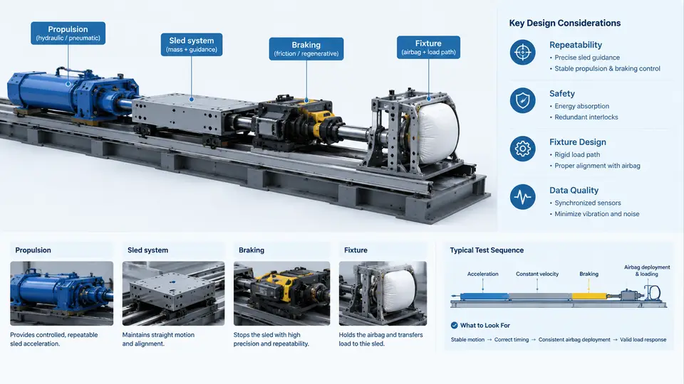
A linear impact test rig is the physical backbone of airbag deployment and occupant-loading validation. Unlike a full-vehicle crash, a sled rig isolates the restraint system from the vehicle body, allowing engineers to control the deceleration pulse, the occupant kinematics, and the airbag deployment environment independently. The rig must deliver a repeatable, measurable, and safe impact event so that the airbag's inflation timing, pressure history, and interaction with the dummy can be evaluated with confidence. This section examines the four subsystems that define the rig: the sled structure, the propulsion system, the braking system, and the fixture design.
Sled System: The Moving Mass and Its Interface
The sled is the moving platform that carries the test buck, the dummy, and the airbag module. Its design is governed by the required velocity change (Δv), the peak deceleration, and the mass of the payload. A typical linear sled consists of a rigid steel or aluminum frame mounted on linear bearings or rails. The rails must be straight within tight tolerances, because any misalignment introduces lateral vibration that corrupts the longitudinal acceleration signal.
The sled mass is a critical parameter. The total moving mass m determines the kinetic energy that must be absorbed by the braking system:
E = 0.5 · m · v²For a 500 kg sled at 50 km/h (13.9 m/s), the kinetic energy is approximately 48 kJ. This energy must be dissipated in a controlled manner, typically over 80–150 ms. The sled frame must therefore be stiff enough to avoid flexural modes below 100 Hz, which would otherwise appear as noise in the accelerometer data. A common design target is a first natural frequency above 200 Hz for the loaded sled.
The sled also carries the mounting interface for the test buck. This interface must be repeatable: the same buck, mounted with the same bolt pattern and torque, should produce the same acceleration response within a few percent. Quick-change plates and dowel-pin location are standard practice to reduce setup variation.
Propulsion: Accelerating the Sled to Target Velocity
The propulsion system must accelerate the sled to the target velocity before the braking phase begins. Three propulsion methods dominate linear impact testing:
- Pneumatic (air) propulsion: Compressed air drives a piston or a shuttle that pushes the sled. It is simple, relatively inexpensive, and well suited to low-to-medium velocities (up to about 60 km/h). The velocity is controlled by the air pressure and the stroke length.
- Hydraulic propulsion: A hydraulic actuator provides higher force and longer strokes, enabling higher velocities and heavier payloads. It offers precise velocity control but requires a hydraulic power unit and careful thermal management.
- Elastic (bungee or spring) propulsion: Stored elastic energy is released to accelerate the sled. This method is mechanically simple and repeatable, but the velocity profile is less controllable and the energy storage is limited.
In all cases, the propulsion system must release the sled cleanly. A sudden release mechanism, such as a pneumatic clamp or a shear pin, is used to hold the sled at the start position and then release it without imparting a lateral impulse. The release timing must be synchronized with the data acquisition system so that the acceleration record begins at a known reference point.
Braking: Shaping the Deceleration Pulse
The braking system is the most critical subsystem for repeatability. It must absorb the sled's kinetic energy and produce a deceleration pulse that matches the target crash pulse. The most common braking method is a set of deformable metal tubes or honeycomb energy absorbers. As the sled moves forward, a probe or piston is forced through the tube, plastically deforming it and generating a nearly constant force. By selecting the tube material, wall thickness, and diameter, engineers can tune the force level and the pulse shape.
An alternative is a hydraulic brake, where a piston forces fluid through an orifice. This allows adjustable force by changing the orifice size, but the force can vary with fluid temperature and velocity. For high repeatability, deformable tubes are preferred because their force-displacement curve is deterministic and insensitive to temperature.
The braking force F and the sled mass m determine the deceleration a:
a = F / mIf the target deceleration is 30 g (294 m/s²) for a 500 kg sled, the required braking force is about 147 kN. This force must be distributed symmetrically to avoid yaw. Two or four brake units are typically used, mounted symmetrically about the sled centerline.
Fixture Design: Holding the Airbag and Dummy Correctly
The fixture, or test buck, is the interface between the sled and the test article. Its design determines whether the airbag deploys into a realistic environment. Key considerations include:
- Geometric fidelity: The buck must reproduce the relevant vehicle structure: the instrument panel, steering column, seat, and floor. For a driver airbag test, the steering column angle and the distance from the airbag module to the dummy chest are critical.
- Stiffness: The buck must be stiff enough that it does not deform under airbag deployment loads. A flexible buck absorbs energy and alters the dummy response. A rule of thumb is that the buck's first mode should be at least three times the highest frequency of interest in the dummy response.
- Adjustability: The buck should allow the dummy position, seat angle, and airbag module location to be adjusted and locked. This enables parametric studies without rebuilding the entire fixture.
- Instrumentation access: The buck must provide mounting points for accelerometers, load cells, and high-speed cameras. Cable routing must be secured to avoid snagging during the impact.
A typical driver-side buck uses a steel frame with a bolted steering column support, an adjustable seat pan, and a footrest. The airbag module is mounted on the steering wheel, which is attached to the column. The dummy is positioned according to the test protocol, typically with the H-point at a specified location and the torso at a defined angle.
System Integration and Repeatability
The four subsystems must work together as a single machine. The propulsion system accelerates the sled to the target velocity; the braking system decelerates it according to the target pulse; the fixture holds the test article in the correct position; and the sled structure transmits the loads without introducing artifacts. Repeatability is verified by running a series of tests with the same setup and comparing the acceleration traces. A well-designed rig should achieve a coefficient of variation below 3% for peak deceleration and below 5% for the pulse duration.
The following diagram shows the architecture of a linear impact test rig, highlighting the flow of energy and the key interfaces between subsystems.
The diagram shows the energy path from propulsion to sled to braking, and the signal path from the dummy and braking system to data acquisition. The dashed feedback line represents the velocity and timing signals used to synchronize the release and the data recording. In practice, the propulsion system is controlled by a release signal, the sled velocity is measured by a light gate or a magnetic pickup, and the braking force is recorded by a load cell. These signals are sampled at 10–20 kHz to capture the high-frequency content of the impact.
When commissioning a new rig, engineers typically start with a low-velocity test (e.g., 20 km/h) and gradually increase to the target velocity. At each step, the acceleration pulse is compared to the target corridor. If the pulse is too high, the braking force is reduced by using a thinner tube or a larger orifice. If the pulse duration is too short, the stroke length is increased. This iterative process continues until the pulse is within tolerance. The final validation is a series of three to five repeat tests at the target velocity, with the coefficient of variation calculated for peak acceleration, pulse duration, and Δv.
In summary, a linear impact test rig is a system of four interacting subsystems. The sled provides the moving mass and the mounting interface; the propulsion system delivers the required velocity; the braking system shapes the deceleration pulse; and the fixture holds the airbag and dummy in a realistic configuration. Repeatability comes from stiffness, symmetry, and deterministic energy absorption. By understanding how these subsystems interact, engineers can design tests that produce reliable, comparable data for airbag deployment and occupant loading validation.