1. Airbag linear impact testing and virtual
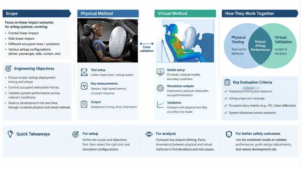
Airbag linear impact testing sits at the intersection of two engineering disciplines that must agree with each other: the physical crash laboratory, where a gas-inflated cushion strikes a calibrated impactor, and the CAE environment, where the same event is reconstructed as a numerical model. This course treats both as one development loop rather than two separate activities. The scope covers the full chain — test rig design, impactor and fixture specification, instrumentation, data reduction, occupant-response metrics, correlated LS-DYNA or PAM-CRASH models, and the decision logic that determines when a virtual result is trustworthy enough to replace a physical test.
Why linear impact testing exists
A full-vehicle frontal or side crash test is expensive, destructive, and slow to iterate. The linear impactor — a guided mass driven along a single axis into a static or semi-static airbag module — isolates the airbag deployment and cushion interaction from the rest of the vehicle structure. That isolation is the point. When a restraint engineer changes a vent hole diameter, a tether length, or a gas generant load, the linear impact rig can show the effect on head or chest acceleration within days, not months.
The rig is not a substitute for the sled or barrier test. It is a screening and diagnostic tool. Its value comes from controllability: impactor mass, velocity, and angle are set independently, the airbag module is mounted in a rigid fixture, and the surrounding structure does not contribute compliance that would mask the cushion's own behavior.
Engineering objectives
Every linear impact program should be traceable to a small set of measurable objectives. In practice these fall into four groups:
- Occupant protection performance — peak head resultant acceleration, HIC15, chest deflection or chest acceleration (depending on the body region under study), and neck injury criteria such as Nij where the head is restrained.
- Deployment robustness — cushion fill time, seam integrity, tether behavior, and the absence of contact with the module housing or instrument panel before full inflation.
- Out-of-position (OOP) behavior — response when the impactor or a surrogate is close to the module at deployment, which drives the choice of inflation profile and venting strategy.
- Model credibility — the degree to which the CAE model reproduces the measured acceleration, pressure, and cushion geometry within an agreed tolerance.
These objectives are not independent. A change that lowers peak head acceleration by softening the cushion may also delay fill time and worsen OOP behavior. The linear impact rig is where that trade-off is first quantified.
Physical and virtual methods: complementary roles
The physical test provides ground truth for a specific configuration. The virtual model provides interpolation and extrapolation across configurations that were never built. Neither is sufficient alone. A model that has never been correlated against a physical linear impact test is a hypothesis; a test program that never feeds a model is a series of isolated data points.
The practical division of labor is usually:
| Activity | Physical test | Virtual model |
|---|---|---|
| Establish baseline response | Primary source | Reconstructed after test |
| Parametric sensitivity (vent, tether, pressure) | Limited by cost and schedule | Primary source |
| OOP and edge-case coverage | Selected cases only | Primary source |
| Final sign-off evidence | Required | Supporting, after correlation |
The correlation step is where the two methods meet. A model is considered correlated when, for the same impactor mass, velocity, and angle, the simulated head acceleration trace matches the measured trace within a defined envelope — typically a peak magnitude deviation under 10–15% and a timing deviation under 2–3 ms for the primary peak. Pressure traces inside the cushion are often the more sensitive indicator of gas-generant and vent modeling errors.
How a linear impact test is actually set up
A representative setup for a driver-side frontal airbag module uses a linear impactor with a hemispherical or flat-faced headform of 6.8 kg or 15 kg, depending on the body region of interest. The module is mounted in a rigid fixture at the steering-wheel angle, and the impactor is accelerated by a pneumatic or servo-hydraulic system to a target velocity between 15 km/h and 35 km/h. The impactor is released at a defined distance from the module face, and the airbag is triggered by a signal synchronized with the impactor's position or velocity.
Instrumentation typically includes:
- Accelerometers in the impactor headform (triaxial) and, where relevant, in the chest or neck surrogate.
- Pressure transducers inside the cushion, sampled at 10 kHz or higher.
- High-speed video at 1000–2000 fps for cushion geometry and seam tracking.
- A load cell or displacement sensor on the impactor drive to confirm the intended velocity profile.
Data reduction follows the standard occupant-safety conventions: acceleration is filtered per SAE J211 (Channel Frequency Class 600 for head, 180 for chest), and HIC15 is computed over the 15 ms window that maximizes the integral. The sign convention must be fixed before any comparison: positive acceleration is defined along the impactor travel direction, and the same convention is applied in the CAE model.
What the virtual model must reproduce
A linear impact CAE model is not simply a mesh of the airbag. It includes the impactor with its mass and initial velocity, the rigid fixture, the folded cushion with its initial fold pattern, the gas generant or inflator model, the venting path, and the contact definitions between cushion, impactor, and fixture. The most common sources of mismatch are:
- Incorrect initial fold geometry, which changes the first contact timing.
- Inflator mass flow rate curve that does not match the tank test data.
- Vent hole effective area that is not updated for fabric stretch.
- Contact stiffness between the cushion and the impactor that is too high or too low.
When the simulated pressure rises faster than the measured pressure, the usual first check is the inflator mass flow curve. When the simulated head acceleration peaks later than the measured trace, the first check is the initial fold and the contact gap between cushion and impactor.
What this course will cover
The remaining chapters build the capability to run this loop end to end. The sequence moves from test rig and instrumentation fundamentals, through occupant-response metrics and data reduction, into airbag modeling, inflator characterization, contact and folding strategy, correlation methodology, and finally the validation and reporting workflow that supports a safety sign-off. Each chapter is written so that the physical and virtual sides are developed together, because in practice they are never separated for long.
By the end of the course, a reader should be able to specify a linear impact test matrix, reduce the resulting data to standard occupant metrics, build and correlate a corresponding CAE model, and judge whether that model is fit to support a design decision. That judgment — not the software or the rig alone — is the real engineering objective.