3. Inflator test bench instrumentation
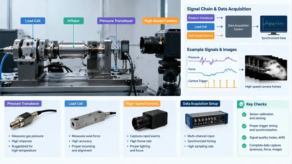
An inflator test bench is only as trustworthy as its measurement chain. The inflator itself may be perfectly repeatable, but if the pressure transducer is mounted on a dead-leg port, if the load cell is loaded off-axis, or if the DAQ sample clock drifts against the camera frame clock, the resulting dataset will be internally inconsistent and useless for CAE correlation. This chapter walks through the four instrument families that define a modern inflator test bench — pressure transducers, load cells, high-speed cameras, and the data acquisition system that binds them — and explains how to select, mount, sample, and synchronize them so that the recorded signals can be compared directly against a validated CAE model.
Pressure Transducers: Capturing the Tank Pressure Pulse
The primary quantitative measurement in an inflator test is the pressure history inside a closed tank or a fixture volume. Pyrotechnic and hybrid inflators can raise tank pressure from ambient to several bar within 10–40 ms, with rise rates exceeding 1000 bar/s. Two transducer technologies dominate this application.
Piezoresistive transducers use a silicon diaphragm with diffused strain gauges in a Wheatstone bridge. They measure absolute or gauge pressure, have excellent low-frequency response (DC to several kHz), and are well suited to tank pressure because the signal is quasi-static after the initial spike. Typical full-scale ranges are 0–10 bar, 0–20 bar, or 0–35 bar, with combined non-linearity and hysteresis around ±0.25 % FS. Their output is a conditioned voltage (e.g., 0.5–4.5 V ratiometric) or a 4–20 mA current loop.
Piezoelectric transducers use a quartz crystal that generates charge proportional to dynamic pressure. They cannot measure static pressure (the charge decays), but they excel at capturing the sharp initial pressure spike with rise times under 10 µs. They are often used in a "pressure spike" channel alongside a piezoresistive tank channel.
Mounting is critical. The transducer should be flush-mounted with the diaphragm coplanar with the tank inner wall. A recessed or dead-leg mounting creates a Helmholtz cavity that attenuates and phase-shifts the pressure signal. If flush mounting is impossible, the cavity volume and port length must be documented and, if significant, compensated in the CAE model. The transducer should also be protected from direct impingement of hot gas and particulates; a sintered metal shield or a small deflection plate is common, but it must not introduce a resonant cavity within the measurement bandwidth.
Load Cells: Measuring Thrust and Reaction Forces
Load cells quantify the force transmitted from the inflator to its mounting structure. This is essential for validating the CAE model's prediction of reaction forces, which drive module housing stress and occupant-adjacent structural response. Two configurations are common:
- Reaction load cell: the inflator is mounted on a rigid fixture supported by one or more load cells. The measured force is the vector sum of the inflator thrust and the gas momentum reaction.
- In-line load cell: the load cell is placed directly in the load path between the inflator and the fixture, measuring axial force only.
Strain-gauge load cells are standard. A typical full-scale range for a driver-side inflator is 2–10 kN, with a safe overload of 150 % FS and a natural frequency above 5 kHz to avoid ringing within the measurement window. The load cell must be loaded through its designed axis; off-axis loading or side moments introduce cross-talk and can permanently zero-shift the cell. Use spherical washer sets or flexure mounts to isolate parasitic loads.
Signal conditioning for load cells is usually a bridge amplifier with excitation (typically 5 V or 10 V DC) and a gain that maps the rated output (e.g., 2 mV/V) to a ±10 V DAQ input. The amplifier bandwidth should be at least 10 kHz to preserve the force rise time. A common pitfall is ground loops between the load cell shield and the DAQ chassis; use a single-point ground and, if necessary, an isolation amplifier.
High-Speed Cameras: Visualizing Deployment and Gas Flow
High-speed cameras provide the spatial context that point sensors cannot. They capture inflator nozzle exit flow, bag unfolding, and any anomalous behavior such as asymmetric deployment or particulate ejection. Typical settings for inflator testing are 5,000–20,000 frames per second (fps) at resolutions of 512×512 to 1024×1024 pixels, with exposure times of 1–10 µs. At 10,000 fps, a 40 ms event yields 400 frames — enough to resolve the primary deployment sequence.
Lighting must be intense and continuous. At 10,000 fps and 5 µs exposure, the sensor receives very little light; high-output LED arrays or metal-halide lamps are required. For flow visualization, schlieren or shadowgraph techniques can reveal density gradients in the gas jet. For bag deployment, a diffuse backlight or a high-intensity front light with a diffuser is preferred.
Camera placement should be orthogonal to the primary motion plane. A common setup uses two cameras: one side view for bag trajectory and one end view for symmetry assessment. Calibration targets (grid or dot patterns) are recorded before the test to establish the pixel-to-millimeter scale and to correct lens distortion. The camera's frame clock must be synchronized with the DAQ; otherwise, correlating a pressure peak at 12.3 ms with a specific frame is guesswork.
Data Acquisition Setup and Synchronization
The DAQ system is the backbone that ties the sensors together. Key specifications include:
| Parameter | Typical Requirement | Why It Matters |
|---|---|---|
| Sample rate | 100 kS/s per channel (minimum 10× highest signal frequency) | Preserves rise time; avoids aliasing |
| Resolution | 16-bit or 24-bit | Resolves small pressure changes on a large offset |
| Input range | ±10 V or ±5 V, software-selectable | Matches sensor output; maximizes dynamic range |
| Anti-alias filter | Analog, cutoff at 0.4× sample rate | Prevents high-frequency noise from folding back |
| Trigger | Hardware trigger from firing current or a pre-trigger TTL | Aligns all channels to t=0 |
| Channel-to-channel skew | < 1 µs | Ensures simultaneous sampling across channels |
Synchronization is achieved by distributing a common trigger and clock. The firing current signal (or a dedicated trigger pulse from the firing box) is routed to the DAQ's external trigger input and to the camera's trigger input. The DAQ begins sampling in pre-trigger mode, continuously buffering data; when the trigger arrives, it captures the pre-trigger buffer plus the post-trigger window. The camera receives the same trigger and begins recording. A common time base — either the DAQ clock or a separate IRIG-B time code — is recorded on an auxiliary channel so that camera frames can be time-stamped relative to the DAQ samples.
Putting It Together: A Reference Instrumentation Chain
The following SVG illustrates a typical inflator test bench instrumentation architecture, showing the signal flow from sensors through conditioning to the DAQ and the synchronization path to the high-speed camera.
Practical Calibration and Verification Checklist
Before any inflator test campaign, the following steps ensure the measurement chain is valid:
- Pressure channel: Apply a known pressure (e.g., 5.00 bar) with a deadweight tester or reference gauge. Record the DAQ voltage. Verify sensitivity (mV/bar) against the calibration certificate. Check zero offset at ambient pressure.
- Load cell channel: Apply a known deadweight (e.g., 1.00 kN) through the load cell's primary axis. Verify output voltage and linearity at 25 %, 50 %, 75 %, and 100 % FS. Check for zero return after unloading.
- Camera: Record a calibration target at the test distance. Verify pixel-to-mm scale and lens distortion. Check frame rate accuracy with a strobe or a known oscillating target.
- Synchronization: Generate a simultaneous electrical pulse on a spare DAQ channel and a visible LED in the camera's field of view. Verify that the LED onset frame corresponds to the pulse time within one frame period.
- Noise floor: With the inflator installed but not fired, record 1 s of data. The peak-to-peak noise on each channel should be less than 0.1 % FS. If not, investigate grounding, shielding, or amplifier gain.
These checks are not optional. A single uncalibrated or unsynchronized channel can invalidate an entire test series and lead to incorrect CAE model adjustments. The instrumentation chain is the foundation of correlation; treat it with the same rigor as the simulation itself.