1. Airbag inflator fundamentals
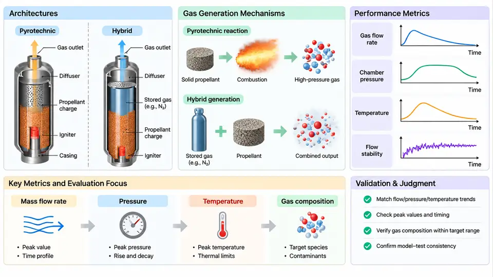
Every airbag restraint system is, at its core, a controlled chemical energy release device. The inflator must convert stored energy into a precisely metered volume of gas within tens of milliseconds, then cool and filter that gas before it reaches the cushion. Understanding how inflators generate gas — and how that generation is quantified — is the prerequisite for designing meaningful tests and for building CAE models that predict real deployment behavior rather than idealized curves.
1.1 Two Dominant Architectures
Production inflators fall into two families: pyrotechnic (solid-propellant) and hybrid (stored-gas augmented). The distinction is not cosmetic; it determines the pressure–time signature, the temperature sensitivity, the particulate load, and the failure modes you will later test for.
Pyrotechnic inflators contain a solid propellant — typically sodium azide-based in legacy designs, or non-azide formulations such as guanidine nitrate with basic copper nitrate in modern units. Ignition of the initiator (a squib or micro gas generator) propagates into the main propellant grain, which deflagrates and produces gas almost entirely from the solid charge. The output is dominated by the propellant burn rate, which follows a pressure-dependent law of the form r = a·Pn, where r is linear burn rate, P is combustion chamber pressure, and a and n are formulation-specific constants. Because the gas comes from a consumable charge, pyrotechnic inflators are compact and cheap, but they run hot and produce more solid residue.
Hybrid inflators combine a small pyrotechnic charge with a pressurized gas reservoir — usually argon or helium at 20–40 MPa in a steel or aluminum pressure vessel. The initiator fires, the pyrotechnic heats and pressurizes the stored gas, and a burst disc or rupture membrane opens to release the mixture through a diffuser. The stored gas supplies most of the volume; the pyrotechnic supplies the thermal energy and the pressure spike that drives it out. Hybrids run cooler, produce less particulate, and offer more tunable output, at the cost of higher mass and a pressure vessel that must survive decades of service.
1.2 Gas Generation Mechanisms
In a pyrotechnic inflator, the sequence is: initiator fires → booster ignites → main propellant deflagrates → gas passes through a filter and coolant → gas exits the diffuser into the cushion. Deflagration, not detonation, is essential — detonation would rupture the housing. The propellant grain geometry (perforated cylinder, disc, or pellet bed) controls the burning surface area and therefore the pressure–time profile.
In a hybrid inflator, the sequence differs: initiator fires → pyrotechnic booster heats the stored gas → pressure rises above the burst disc threshold → disc ruptures → gas expands through the diffuser. The stored gas does the volumetric work; the booster mainly raises temperature and pressure. This is why hybrid output is less sensitive to propellant burn-rate variation but more sensitive to initial fill pressure and ambient temperature.
Both architectures must manage three byproducts: heat, particulate, and residual pressure. The filter and coolant pack — often a knitted metal mesh with a ceramic or wire-mesh heat sink — removes slag and drops gas temperature from over 1000 °C at the combustion zone to a cushion-safe range. If the filter is undersized, particulate escapes and can burn the cushion fabric; if the coolant is insufficient, the cushion may over-pressurize or the occupant may be exposed to hot gas.
1.3 Performance Metrics That Matter
Inflator performance is characterized by a small set of measurable quantities, each of which maps directly to a CAE model input or a validation checkpoint.
| Metric | Definition | Typical Range / Note |
|---|---|---|
| Peak pressure (Pmax) | Maximum pressure in the tank test fixture | Driver side: 200–400 kPa in a 60 L tank |
| Time to peak (tpeak) | Interval from initiator trigger to Pmax | 20–50 ms; defines cushion fill speed |
| Mass flow rate (ṁ) | Gas mass leaving the diffuser per unit time | Derived from tank pressure rise and orifice area |
| Gas yield (ngas) | Moles of gas produced per gram of propellant | Pyrotechnic: 0.02–0.04 mol/g; hybrid: stored gas dominates |
| Exit temperature (Texit) | Gas temperature at diffuser outlet | Pyrotechnic: 400–700 °C; hybrid: 200–400 °C |
| Particulate mass | Solid residue collected downstream of filter | < 1 g for modern pyrotechnic; lower for hybrid |
The standard measurement is the tank test: the inflator is fired into a sealed, known-volume tank (commonly 60 L or 100 L), and the pressure–time history is recorded. From that single curve, you can extract Pmax, tpeak, and — using the ideal gas law with a correction for temperature — the mass flow rate. The tank test is the bridge between physical testing and CAE: the measured pressure curve becomes the target that the simulation must reproduce.
1.4 From Measurement to Model Input
For CAE validation, the inflator is usually represented as a pressure–time or mass flow–time boundary condition applied at the diffuser outlet. The choice matters. A pressure–time curve is easy to apply but ignores back-pressure from the cushion; a mass flow–time curve is more physically correct because the inflator's output depends on the pressure difference across the diffuser, not on absolute pressure alone.
Consider a worked example. A driver-side pyrotechnic inflator is fired into a 60 L tank at 23 °C. The recorded peak pressure is 320 kPa at 35 ms. Using the ideal gas law with an assumed gas temperature of 500 K at peak, the moles of gas in the tank are:
n = P·V / (R·T)
  = (320,000 Pa)(0.060 m³) / (8.314 J/mol·K)(500 K)
  = 19,200 / 4,157
  ≈ 4.62 mol
If the propellant charge is 45 g, the gas yield is 4.62 / 45 ≈ 0.103 mol/g — higher than the typical range because the tank gas is not all propellant-derived; air initially in the tank contributes. Correcting for the initial 2.45 mol of air (at 101.3 kPa, 23 °C) gives a propellant-derived yield of (4.62 − 2.45) / 45 ≈ 0.048 mol/g, which is consistent with a guanidine nitrate formulation. This kind of back-calculation is exactly what you do when preparing a CAE input deck: you convert a measured tank curve into a mass flow boundary condition, then verify that the simulation reproduces the same tank pressure.
1.5 What the Architecture Means for Testing and CAE
The architecture determines your test matrix and your model fidelity requirements. Pyrotechnic inflators are sensitive to propellant temperature and grain geometry, so you test across −35 °C, 23 °C, and +85 °C. Hybrid inflators are sensitive to fill pressure and burst disc tolerance, so you test across the same temperatures but also verify the pressure vessel's leak rate and the disc's rupture pressure. In CAE, a pyrotechnic inflator may need a burn-rate model if you are studying combustion chamber dynamics; a hybrid inflator may need a two-phase model if you are studying gas expansion and particulate transport.
The metrics in Section 1.3 are not just acceptance criteria — they are the calibration targets for the model. If your simulation reproduces Pmax but not tpeak, your mass flow profile is wrong. If it reproduces both but the cushion fill is slow, your diffuser orifice model is too restrictive. The next chapters build on this foundation: you will learn how to instrument the tank test, how to derive the boundary condition, and how to validate the model against the physical curve.