3. Quasi-static tensile testing of airbag f
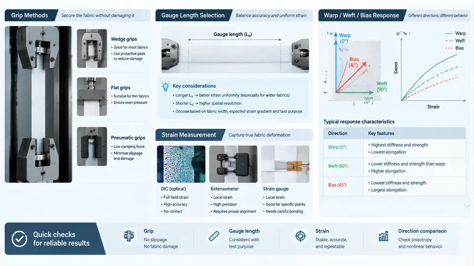
Quasi-static tensile testing is the foundation of every airbag fabric material model. Before any calibration can be trusted, the raw force–displacement data must be acquired under controlled, repeatable conditions. Airbag fabrics are woven, coated, and highly anisotropic, so the test method itself strongly influences the measured modulus, strength, and failure strain. This section covers grip selection, gauge length, strain measurement, and how to interpret warp, weft, and bias responses.
Specimen Geometry and Grip Methods
Airbag fabrics are typically tested as strip specimens (25–50 mm wide) or as full-width raveled strips. Two grip families dominate:
- Mechanical wedge grips — serrated or smooth jaws clamp the specimen. Fast to set up, but the jaw face introduces stress concentrations that frequently cause jaw-line failure in high-tenacity nylon 6.6.
- Capstan / roller grips — the fabric wraps around a roller and is self-tightening under load. This reduces jaw-line failure and is preferred for coated fabrics and for bias tests where shear deformation is large.
For strip specimens, a thin elastomeric facing or emery cloth between jaw and fabric improves grip without cutting yarns. A common practical rule: if more than ~20% of specimens fail within 5 mm of the jaw, the grip method is suspect and should be changed before calibration data is used.
Gauge Length Selection
Gauge length controls the ratio of gripped region to free region and therefore the uniformity of strain. For woven airbag fabric, a gauge length of 100 mm is a widely used baseline for warp and weft strip tests, with a specimen width of 50 mm. Shorter gauges (25–50 mm) amplify grip effects and are only appropriate when the material is very extensible or when the test fixture is space-constrained. Longer gauges (200 mm) reduce grip influence but increase the chance of capturing weave irregularities and require stiffer frames.
The gauge length must be recorded and used consistently, because engineering strain is computed as ΔL/L₀. A change from 100 mm to 50 mm without updating L₀ will double the apparent strain at the same displacement.
Strain Measurement
Crosshead displacement is not a valid strain measure for airbag fabric. Compliance in the load train, grip slip, and yarn crimp removal all contribute to crosshead motion that is not specimen strain. Three measurement approaches are used:
- Extensometer — a clip-on or non-contacting extensometer measures displacement over a defined gauge section. This is the reference method for modulus determination.
- Digital Image Correlation (DIC) — speckle pattern tracked by cameras. Excellent for bias tests where shear bands form and strain is non-uniform.
- Crosshead with compliance correction — acceptable only for comparative ranking, not for modulus calibration.
Warp, Weft, and Bias Response
Woven airbag fabric is orthotropic. The three principal test directions give fundamentally different curves:
| Direction | Loading mode | Typical curve shape | Key parameter |
|---|---|---|---|
| Warp (0°) | Yarn tension along machine direction | Initial crimp region, then stiff linear region | Warp modulus, warp strength |
| Weft (90°) | Yarn tension across machine direction | Similar to warp but often lower crimp | Weft modulus, weft strength |
| Bias (45°) | Shear-dominated, yarn rotation | Low initial stiffness, large strain, late stiffening | Shear modulus, locking strain |
The bias test is the most sensitive to grip method and gauge length because the specimen undergoes large shear deformation. Capstan grips or wide strip specimens with DIC are strongly recommended. The bias curve typically shows a low-stiffness “trellis” region where yarns rotate, followed by a sharp stiffening when yarns lock against each other. This locking strain is a critical input for airbag deployment simulations.
Practical Test Sequence and Data Reduction
A reproducible quasi-static test for airbag fabric follows this sequence:
- Condition specimens at 23 ± 2 °C and 50 ± 5% RH for at least 24 h.
- Measure and record specimen width and thickness at three points; use the average for stress calculations.
- Mount the specimen with the yarn direction aligned to the load axis. For bias tests, align the 45° direction.
- Set gauge length (e.g., 100 mm) and crosshead speed. A strain rate of 0.01–0.1 s⁻¹ is typical for quasi-static.
- Preload to 1–2 N to remove slack, then zero the extensometer.
- Run to failure or to a defined strain limit (e.g., 30% for bias).
- Record force, displacement, and extensometer strain at 100 Hz minimum.
Data reduction: compute engineering stress as force divided by initial cross-sectional area (width × thickness). Compute engineering strain from the extensometer. For modulus, fit a linear regression over the initial linear region (typically 1–5% strain for warp/weft, 5–15% for bias). Report the regression range and R² value.
Interpreting the Results
Warp and weft curves usually show an initial toe region (crimp removal), a linear region (yarn extension), and a yield/plateau region before failure. The bias curve shows a low-stiffness shear region, a transition, and a stiff locking region. If the bias curve looks similar to the warp curve, the specimen is likely misaligned or the gauge length is too short.
Typical values for a 420 denier nylon 6.6 airbag fabric (example, not a specification): warp modulus ~2.5 GPa, weft modulus ~2.2 GPa, bias shear modulus ~0.05 GPa, bias locking strain ~25–35%. These are illustrative and must be replaced by measured data for any real calibration.
Common Pitfalls and Troubleshooting
- Jaw-line failure — switch to capstan grips or add elastomeric facing. Check that specimen edges are clean and parallel.
- Specimen slippage — monitor for a sudden drop in force or a step in the displacement record. Increase clamping pressure or use a rougher jaw face.
- Misalignment — warp/weft yarns must be parallel to the load axis. A 5° misalignment can reduce measured modulus by 10–15%.
- Bias test artifacts — if the bias curve shows a sharp initial peak, the specimen is likely pinched or the gauge length is too short. Increase gauge length and verify free rotation at grips.
- Extensometer slip — verify knife edges are seated on the specimen, not on the grip. Re-zero before each test.
Recording these conditions in a test log is essential. A minimal log entry should include: specimen ID, direction, width, thickness, gauge length, grip type, strain measurement method, crosshead speed, preload, failure location, and modulus regression range. Without this metadata, the resulting material model cannot be traced back to a valid test.
The data from these quasi-static tests becomes the input for the calibration workflow in later chapters. Warp and weft curves constrain the in-plane tensile response; the bias curve constrains the shear response. Together they define the orthotropic behavior that a fabric material model must reproduce.