1. Airbag fabric fundamentals
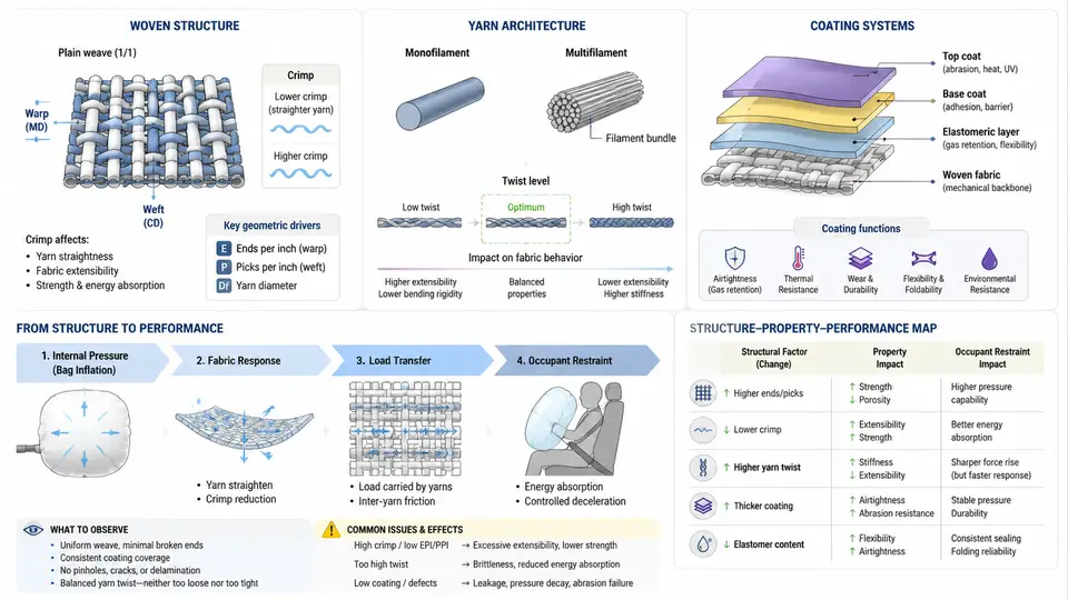
An airbag is not a balloon. It is a precision-engineered pressure vessel that must inflate in roughly 20–50 milliseconds, absorb the kinetic energy of a 75 kg occupant moving at 50 km/h, and then vent that energy in a controlled manner. Every one of those behaviors is determined long before the module is assembled — at the level of the fabric. Understanding woven structure, yarn architecture, and coating systems is therefore the foundation for every subsequent topic in this course, including material model calibration.
Why Fabric, Not Film or Metal
The dominant material for driver and passenger airbags is woven polyamide 6.6 (nylon 6.6) fabric, typically 420–840 denier, with areal weights between 180 and 260 g/m² for coated grades. Nylon wins for three reasons: high specific tensile strength, excellent energy absorption through yarn elongation (breaking elongation of 20–25%), and the ability to be woven into a dense, dimensionally stable structure at low cost. Polyester (PET) appears in some side airbags and non-coated applications, but its lower elongation and higher stiffness make it less forgiving in high-pressure frontal deployments.
The fabric must simultaneously satisfy conflicting requirements: it must be strong enough to resist the internal pressure pulse (peak pressures of 200–400 kPa in a driver module), yet permeable enough — or vented enough — to allow controlled deflation. It must fold into a package of roughly 100 mm diameter, survive 15 years of thermal cycling, and resist seam slippage under biaxial loading.
Woven Structure and Yarn Architecture
Airbag fabric is a plain-weave construction. Warp yarns (machine direction) and weft/fill yarns (cross direction) interlace in a 1×1 pattern. This is not an arbitrary choice: plain weave maximizes interlacing points per unit area, which locks the yarns in place, limits crimp interchange, and produces a nearly isotropic in-plane response. The trade-off is that plain weave has the lowest tear strength of any weave — a critical consideration for seam design.
Key architectural parameters that directly control mechanical response:
- Yarn linear density (denier): 420D, 630D, and 840D are standard. Higher denier means thicker yarns, higher breaking force per yarn, but also a coarser fabric that is harder to pack.
- Thread count (ends/inch and picks/inch): Typically 40–60 in each direction. Higher thread count increases cover factor and reduces permeability, but raises fabric stiffness and cost.
- Crimp: The waviness of yarns as they interlace. Crimp allows the fabric to extend under load as yarns straighten — this is the first stage of the stress–strain curve and is highly sensitive to weaving tension and finishing.
- Weave balance: The ratio of warp to weft crimp. An unbalanced weave produces anisotropic deployment behavior and asymmetric seam loading.
The stress–strain response of the base fabric is therefore not a single material property but a structural response: initial crimp decrimping (low modulus), yarn straightening and lateral compression (transition), and finally yarn tensile extension (high modulus, roughly 8–12 GPa for nylon 6.6). Any material model that treats airbag fabric as a simple isotropic elastic sheet will fail to capture this three-stage behavior.
Coating Systems and Their Function
Uncoated nylon fabric is permeable: inflation gas escapes through the inter-yarn gaps. For driver and passenger airbags, this is unacceptable because the bag must hold pressure long enough to restrain the occupant. Coatings solve this by sealing the fabric surface.
Three coating families dominate:
| Coating type | Typical material | Add-on weight | Primary function | Trade-offs |
|---|---|---|---|---|
| Silicone | Addition-cure PDMS | 25–60 g/m² | Low permeability, high flexibility, wide temperature range (−40 to +120 °C) | Higher cost, can migrate, affects folding stiffness |
| Polyurethane (PU) | Solvent or water-based PU | 20–50 g/m² | Good permeability barrier, lower cost than silicone | Lower thermal stability, hydrolysis risk in humid environments |
| Neoprene / chloroprene | CR latex | 30–70 g/m² | Excellent heat resistance, used in high-temperature zones | Heavier, stiffer, being phased out in some regions |
The coating is applied to one or both sides. One-side coating is common for driver bags; two-side coating is used where both faces must resist gas permeation or where the fabric contacts hot gas directly. The coating also affects seam performance: coated fabric requires seam sealing or taped seams to prevent gas leakage through stitch holes.
Permeability is quantified as volumetric flow rate per unit area per unit pressure differential (e.g., L/dm²/min at 500 Pa). A typical coated driver fabric might measure 0.1–1.0 L/dm²/min, while an uncoated fabric can exceed 50 L/dm²/min. This single number determines how long the bag holds pressure and therefore how the occupant decelerates.
How Fabric Architecture Maps to Occupant Restraint
The chain from yarn to occupant is direct and measurable:
- Yarn denier and thread count set the fabric's tensile stiffness and breaking strength, which determine the maximum internal pressure the bag can sustain without bursting.
- Crimp and weave balance control the initial compliance of the bag — how quickly it expands to fill the available volume before becoming stiff.
- Coating permeability governs the pressure decay curve, which in turn governs the deceleration pulse experienced by the occupant.
- Seam construction (stitch type, thread, seam allowance) interacts with weave tear strength to determine whether the bag fails at the seam or holds.
In a typical driver-side restraint event, the bag must reach full inflation in 25–35 ms and then vent to near-ambient pressure within 80–120 ms. If the fabric is too permeable, the bag deflates before the occupant loads it, and the occupant strikes the steering wheel. If it is too impermeable, the bag acts as a rigid surface and increases injury risk. The coating and venting strategy must be tuned together.
Practical Implications for Testing and Calibration
When you receive a fabric for testing, the first step is to record the architectural parameters: denier, thread count, weave type, coating type and add-on, and areal weight. These are not background information — they are the inputs that explain every subsequent measurement. A biaxial tensile test at 0°/90° will show a distinct toe region whose length correlates with crimp. A permeability test will show a pressure-dependent flow rate that depends on coating integrity. A seam strength test will show whether the weave can resist yarn pull-out.
For the material model calibration work later in this course, the fabric architecture defines the model's structure. An orthotropic elastic model needs the four independent constants (E₁, E₂, ν₁₂, G₁₂) — these come from biaxial tests aligned with the weave. A damage model needs the failure strains in warp and weft — these come from tensile tests to rupture. A permeability model needs the coating's flow–pressure relationship — this comes from a dedicated permeability fixture. None of these can be guessed from a data sheet alone; they must be measured on the actual fabric lot.
The key insight for this chapter is that airbag fabric is a structured material. Its behavior is not the behavior of nylon; it is the behavior of a woven architecture made from nylon, coated with a polymer, and assembled with seams. Every subsequent test and every calibration decision must respect that structure.