1. Airbag drop tower testing and impact CAE
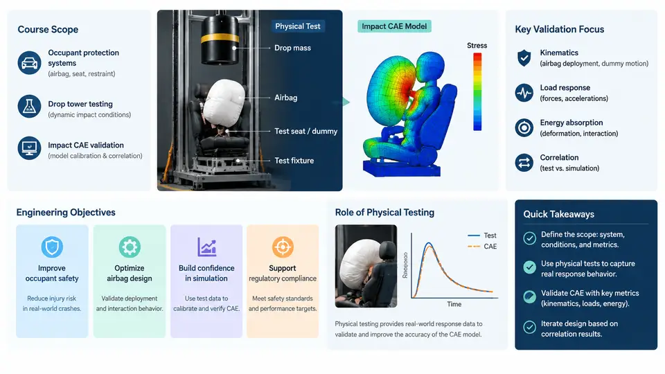
Airbag deployment is one of the most safety-critical events in a vehicle crash. Within a few tens of milliseconds, a pyrotechnic inflator must release gas, a folded cushion must unfurl without snagging, and the resulting pressure field must cushion an occupant whose head and chest are already moving toward the module. If any of these steps is mistimed or misdirected, the airbag can injure rather than protect. Because the full vehicle crash test is expensive, destructive, and difficult to instrument at the module level, engineering teams rely on two complementary tools: the airbag drop tower test and impact CAE validation. This chapter defines the scope of the course, states the engineering objectives that drive both activities, and explains why physical testing remains indispensable even in a simulation-dominated development process.
What the Drop Tower Actually Simulates
A drop tower is a vertical test rig in which a weighted sled or impactor is raised to a defined height and released to strike an airbag module, a folded cushion, or a complete occupant restraint assembly. The drop height sets the impact energy; the mass of the falling body sets the momentum; the contact face geometry sets the loading distribution. By controlling these three variables, engineers reproduce the essential mechanics of an occupant-to-airbag interaction without building a full vehicle.
The key insight is that a drop tower does not reproduce a crash — it reproduces a boundary condition. The test isolates the airbag module and the adjacent structure so that deployment kinematics, cushion pressure, seam behavior, and tether forces can be measured directly. This isolation is what makes the drop tower valuable: it removes the noise of vehicle-level deformation and lets engineers observe the airbag as a system in its own right.
Engineering Objectives of the Course
This course is organized around four engineering objectives that mirror how a real restraint development program is structured:
- Characterize the airbag as a dynamic system. Establish how inflator output, cushion volume, venting, and fabric permeability interact to produce the pressure–time and force–time histories that an occupant actually experiences.
- Build and validate a CAE model that predicts those histories. Develop a finite element model of the module and cushion, calibrate it against drop tower measurements, and quantify the model's predictive confidence.
- Use the validated model to support design decisions. Apply the model to evaluate inflator variants, cushion geometry changes, and venting strategies before committing to hardware.
- Close the loop between test and simulation. Define the instrumentation, data reduction, and correlation metrics that make test and CAE comparable on equal terms.
These objectives are deliberately ordered. A model cannot be validated before the physical behavior is understood, and a validated model is only useful if it feeds back into design. The course follows this dependency chain rather than treating test and simulation as parallel activities.
Why Physical Testing Still Matters
Modern CAE tools can simulate airbag deployment with impressive fidelity, yet physical testing remains mandatory for several reasons. First, material behavior under extreme strain rates is not fully characterized. Airbag fabric, coatings, and inflator propellant all behave differently at the strain rates and temperatures seen in a deployment than they do in quasi-static coupon tests. Second, manufacturing variability is real. Fold patterns, seam stitching, and inflator lot-to-lot differences introduce scatter that a nominal CAE model does not capture. Third, regulatory and customer requirements explicitly demand physical evidence. A simulation alone cannot certify a restraint system.
The drop tower occupies a specific niche in this landscape. It is more controlled than a sled test and far cheaper than a full vehicle crash, yet it retains the real hardware — the actual inflator, the actual folded cushion, the actual module housing. This makes it the ideal bridge between component-level material testing and full-system validation.
Key distinction: A drop tower test validates the airbag module as a subsystem. A full vehicle crash test validates the restraint system in its installed environment. CAE validation must be scoped to match the test it is compared against — a model calibrated on drop tower data is not automatically valid for vehicle-level predictions.
The Test–CAE Validation Loop
The relationship between drop tower testing and impact CAE is iterative, not sequential. The diagram below shows the core loop: a physical test produces measured responses; those responses are compared against a CAE prediction; the discrepancy drives model calibration; the calibrated model is then used to predict a new configuration, which is verified by a new test.
Scope Boundaries and What This Course Does Not Cover
To keep the material focused, it is worth stating what falls outside the scope. This course does not cover full vehicle crashworthiness, occupant injury criteria (HIC, chest deflection, etc.) as a primary topic, or regulatory certification procedures in detail. Those subjects belong to vehicle-level safety development. Instead, the course concentrates on the module-level physics and the test–CAE correlation methodology that supports it.
Similarly, the course treats the inflator as a boundary condition with a specified mass flow rate and gas temperature, rather than modeling propellant combustion chemistry. This is consistent with standard industry practice: the inflator is characterized separately on a tank test, and its output is supplied to the airbag model as a time-dependent input.
Reference Parameters for the Course Examples
Throughout the course, examples will use a consistent set of reference parameters so that results can be compared across chapters. These values are representative of a passenger-side airbag module and are provided as teaching inputs, not as measured data from a specific program.
| Parameter | Symbol | Reference Value | Unit |
|---|---|---|---|
| Impactor mass | m | 25 | kg |
| Drop height | h | 1.2 | m |
| Impact velocity | v₀ | ≈ 4.85 | m/s |
| Cushion volume (deployed) | V | 60 | L |
| Vent orifice diameter | d_vent | 30 | mm |
| Inflator peak mass flow | ṁ_max | ≈ 2.5 | kg/s |
| Ambient temperature | T_amb | 23 | °C |
The impact velocity follows from energy conservation: v₀ = √(2gh), giving approximately 4.85 m/s for a 1.2 m drop. This is a moderate-severity condition suitable for observing deployment kinematics without immediately rupturing the cushion. Higher-severity conditions will be introduced in later chapters when discussing seam strength and venting limits.
Practical note: Always record the actual drop height and impactor mass in the test log, even if they match the nominal values. Small deviations in release height or friction in the guide rails can shift the impact velocity by several percent, which directly affects the energy available for cushion pressurization.
What You Should Be Able to Do After This Chapter
By the end of this chapter, you should be able to explain why a drop tower is used instead of a full vehicle test for airbag module characterization, identify the four engineering objectives that structure the course, and describe the iterative loop between physical testing and CAE validation. You should also recognize the reference parameter set that will be used consistently in later chapters and understand that these values are teaching inputs rather than measured results.
The next chapter begins the technical work by examining the drop tower facility itself — its mechanical configuration, instrumentation chain, and data acquisition setup — so that the measured responses used in the validation loop can be interpreted with confidence.