3. CAE model setup for airbag deployment
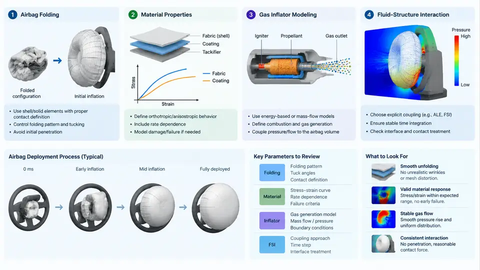
An airbag deployment simulation is only as trustworthy as the model behind it. In an explicit solver such as LS-DYNA, Radioss, or Abaqus/Explicit, the airbag is not a single object but a chain of coupled sub-models: a folded fabric membrane, a gas source, and the fluid-structure interaction (FSI) that links internal pressure to membrane motion. This chapter walks through the four setup pillars — folding, material properties, inflator modeling, and FSI approach — and shows how each choice propagates into the deployment kinematics you later compare against video.
3.1 Airbag Folding
Folding converts a flat, unstressed fabric blank into the compact package that sits behind the module cover. The solver must reproduce this geometry because the initial fold pattern dictates how the bag unfolds, where fabric contacts itself, and how quickly the cushion reaches the occupant. Two families of methods dominate practice.
Explicit geometric folding builds the folded state directly in the pre-processor. The flat mesh is partitioned into panels, then each panel is rotated and translated through a sequence of rigid-body transforms until the bag matches the CAD package envelope. This is fast and gives full control, but the resulting mesh may contain highly distorted elements and self-intersections that trigger negative-volume errors at the first time step.
Implicit or quasi-static folding presses the bag into a cavity using rigid plates. The fabric is deformed under contact, and the final configuration is exported as the initial state for the explicit run. This produces more realistic wrinkle patterns and residual stresses, at the cost of a longer setup and a need to map stresses carefully.
Regardless of method, three checks are mandatory before proceeding:
- Element quality: keep the minimum Jacobian above roughly 0.3 and avoid inverted shells; a single inverted element can abort the run.
- Initial penetration: run a contact initialization pass so the folded layers do not start interpenetrated.
- Mass scaling: if folding required artificial mass, remove it before the deployment run, or the inertia will distort early-time kinematics.
3.2 Material Properties for the Fabric
Airbag fabric is a woven nylon (typically 6.6) or polyester. Its mechanical response is strongly anisotropic and nearly incompressible in the plane, so an isotropic elastic model is usually inadequate for anything beyond a first-order check. The common choices are:
| Model | Typical use | Key inputs |
|---|---|---|
| Orthotropic elastic (MAT_002 style) | Fast concept studies | E1, E2, ν12, G12, density |
| Fabric / membrane (MAT_034, MAT_235) | Production airbag models | Warp/weft moduli, shear curve, porosity |
| Hyperelastic (Mooney-Rivlin) | Coated or silicone-treated fabric | C10, C01, D1 |
For a 470 dtex nylon 6.6 plain weave, representative example values are E_warp ≈ 2.5 GPa, E_weft ≈ 2.3 GPa, and a shear modulus that is an order of magnitude lower. These are illustrative starting points, not measured data — always replace them with coupon test results (ASTM D5035 strip tensile, ASTM D1388 bending) for the specific fabric lot.
Two additional properties matter for deployment:
- Permeability / porosity: controls venting through the fabric. It is often modeled as a leakage coefficient or a porous shell, and it strongly affects peak pressure.
- Strain-rate sensitivity: nylon stiffens at high strain rates. If your solver supports it, supply a rate-dependent curve; otherwise document the omission as a known limitation.
3.3 Gas Inflator Modeling
The inflator is the energy source. In CAE it is rarely modeled as geometry; instead it is represented by a mass-flow and temperature history injected into a control volume. Three levels of fidelity are common:
- Uniform pressure (UP) / tank test curve: the simplest approach. A measured or supplier-provided pressure-time curve is applied to the bag as a uniform internal pressure. Fast, but it cannot capture gas dynamics or jet effects.
- Control-volume (CV) method: the bag interior is treated as one or more thermodynamic control volumes. The inflator supplies mass flow ṁ(t) and temperature T(t); the solver integrates the ideal-gas or JWL equation of state to get pressure, then applies it to the fabric. This is the workhorse for occupant-restraint models.
- CFD / corpuscular (particle) method: the gas is discretized as particles or a CFD mesh, resolving jets, temperature gradients, and venting. Used when the deployment sequence itself is under study.
A typical CV input deck specifies the inflator as a table of mass flow versus time, plus the gas temperature and the specific heat ratio γ. For a driver-side inflator, the mass flow may rise to ~2–4 kg/s within 10 ms and then decay. The control volume then computes:
*AIRBAG_INFLATOR
$   t(ms)    mdot(kg/s)   T(K)
    0.0       0.0          300
    2.0       1.8          900
    5.0       3.2          950
   10.0       2.1          900
   20.0       0.4          700
   30.0       0.0          600
The pressure inside the CV follows from the ideal-gas relation P = m R T / V, where V is the instantaneous bag volume computed from the deformed membrane. This coupling — volume feeds pressure, pressure drives the membrane — is the essence of FSI.
3.4 Fluid-Structure Interaction Approaches
FSI is where the airbag model becomes a coupled problem. The explicit solver advances the structural mesh; the gas model advances the thermodynamic or CFD state; the two exchange volume and pressure at each time step. The main approaches are summarized below.
The choice of FSI method depends on the question being asked. For occupant injury assessment, the CV method is standard because it is fast and stable. For studying the deployment sequence itself — jet formation, fabric flutter, vent timing — a CFD or particle method is required, at a cost of one to two orders of magnitude in runtime.
3.5 A Reproducible Setup Checklist
The following example configuration summarizes a driver-side airbag model suitable for a first deployment study. Values are illustrative and must be replaced with supplier data.
# Airbag deployment — example setup
Fabric:      nylon 6.6, 470 dtex, plain weave
Shell:       Belytschko-Tsay, 5 integration points
Folding:     quasi-static plate press, 4 panels
Inflator:    CV method, mass flow table (0–30 ms)
Gas:         ideal gas, gamma = 1.4, T = 900 K
Venting:     2 vents, area 500 mm^2 each
Contact:     single surface, friction 0.2
Time step:   auto, scale to 1e-6 s
Termination: 80 ms
After the run, verify three things before comparing to video: (1) the bag reaches full deployment within the expected time window (typically 25–35 ms for a driver bag); (2) peak internal pressure is within the supplier's tank-test envelope; (3) no element erosion or negative volume occurred. If the bag deploys too slowly, check the mass-flow table and the vent area first. If pressure spikes unrealistically, the control volume may be too small or the gas temperature too high. If the fabric tears early, revisit the material shear curve and the fold-induced stress state.
With the model built and validated against a baseline deployment, the next step is to extract the kinematic and pressure signals that will be compared frame-by-frame against the high-speed video — the subject of the following chapter.