1. Airbag deployment validation landscape
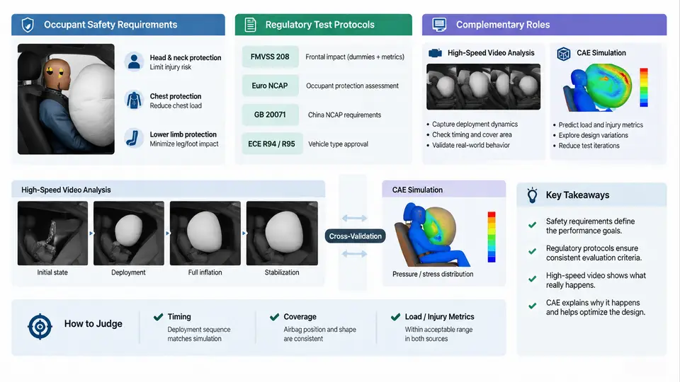
An airbag is a pyrotechnic restraint device that must perform correctly exactly once, within tens of milliseconds, under conditions that are never fully repeatable. Validating that performance is therefore not a single test but a layered evidence system: regulatory compliance tests that establish a legal baseline, occupant-safety engineering targets that go beyond the regulation, and two complementary analysis methods — high-speed video and CAE simulation — that explain what happened and why. This chapter maps that landscape before the course moves into the mechanics of each method.
1.1 What the airbag must actually do
The functional requirement is usually stated as a set of occupant injury criteria measured on an instrumented Anthropomorphic Test Device (ATD, or "dummy"). For a frontal driver airbag under US FMVSS 208, the primary criteria at 50 km/h rigid-barrier impact are:
- HIC15 (Head Injury Criterion over a 15 ms window) ≤ 700 for the 50th-percentile male ATD.
- Peak chest deflection ≤ 63 mm (Hybrid III 50th male).
- Peak axial femur load ≤ 10 kN per leg.
- Neck injury criteria (Nij, tension, compression) within specified envelopes.
These numbers are the pass/fail floor, not the design target. A production program typically targets 15–25 % margin below the limit, because vehicle-to-vehicle build variation, temperature extremes, and inflator lot variation all shift results. A deployment that "just passes" at nominal conditions is a field-risk liability.
Two physical constraints dominate the design space. First, the airbag must inflate fast enough to be in position before the occupant's head reaches the steering wheel — typically the bag must be fully deployed within 30–50 ms of the crash pulse. Second, it must not inflate so aggressively that the deploying bag itself injures an out-of-position (OOP) occupant. These two requirements pull in opposite directions, and the entire validation program exists to prove that both are satisfied simultaneously.
1.2 Regulatory protocols and their structure
Regulatory tests are standardized so that results are comparable across vehicles and laboratories. The key protocols relevant to frontal airbag validation are:
| Protocol | Impact condition | Primary purpose |
|---|---|---|
| FMVSS 208 | 0°, 40 km/h & 50 km/h rigid barrier; 30° angled | Occupant injury criteria compliance |
| FMVSS 208 OOP | Static deployment, 0–6 in from module | Low-risk deployment for small occupants |
| ECE R94 | 40 % offset deformable barrier, 56 km/h | European frontal compliance |
| Euro NCAP | Offset + full-width + MPDB | Rating beyond legal minimum |
| FMVSS 226 | Side pole / ejection | Ejection mitigation (side airbag) |
Each protocol fixes the barrier type, impact speed, impact angle, ATD type and seating position, and the measurement channels. The test laboratory records the crash pulse (vehicle deceleration vs. time), the airbag pressure or inflator current, and the ATD channel data. The pass/fail decision is made against the criteria in the regulation, not against a simulation.
1.3 Where high-speed video fits
High-speed video is the only method that directly observes the physical deployment. A typical setup uses 1000–2000 fps cameras positioned to capture the bag from the driver's side, from above, and from the front. The video answers questions that sensor data cannot:
- Deployment trajectory: Does the bag unfold symmetrically, or does it "punch" toward the occupant on one side?
- Timing: At what frame does the bag first contact the occupant? This is measured by frame counting from the trigger signal, which is recorded on the same time base as the video.
- Interaction: Does the occupant's head slide off the bag, or does the bag catch it? Does the bag bottom out on the steering wheel?
- Failure modes: Fabric tears, seam separation, tether breakage, or inflator housing rupture are all visible.
The limitation is equally important: video shows the result of the deployment but not the internal pressure, stress, or gas flow that produced it. It is a surface observation. It also cannot be run before a physical prototype exists.
1.4 Where CAE simulation fits
CAE — typically explicit finite-element analysis in LS-DYNA or PAM-CRASH — models the same event numerically. A frontal airbag model includes:
- A folded bag mesh (shell elements) with the actual fold pattern from the CAD data.
- A gas generator model — either a uniform-pressure (UP) or a corpuscular-particle (CPM) inflator model, driven by a tank-test mass-flow curve.
- A contact definition between bag, steering wheel, and ATD.
- The vehicle crash pulse applied to the steering column and body structure.
The simulation predicts bag pressure, bag shape vs. time, and ATD injury criteria. Its value is that it can be run before any hardware exists, and it can be interrogated at any point in space and time — internal pressure, membrane stress, contact force — which video cannot provide.
Its limitation is that it is only as good as its inputs. A wrong fold pattern, an inaccurate tank curve, or a poorly calibrated ATD model will produce a plausible-looking but wrong result. This is why simulation is never used alone for regulatory compliance.
1.5 The complementary validation loop
The two methods are not alternatives; they are a closed loop. The diagram below shows how they feed each other during a typical development cycle.
The loop works as follows. CAE proposes a design — fold pattern, inflator output, vent size, tether length. A physical sled or barrier test is run with that design, and high-speed video plus ATD data are recorded. The video is compared frame-by-frame against the simulated bag shape at the same timestamps. If the bag unfolds differently — say the simulation shows symmetric unfolding but the video shows the top tether releasing early — the model is updated and the loop repeats. Only when the simulation correlates with the physical test across multiple conditions is the model trusted to predict new conditions without a test.
1.6 Practical correlation criteria
Correlation is judged on specific, measurable quantities, not on visual similarity alone. A typical correlation scorecard for a frontal driver airbag includes:
| Quantity | Source (test) | Source (CAE) | Acceptance guide |
|---|---|---|---|
| Time to full deployment | Video frame count | Bag volume / pressure peak | ±2 ms |
| Bag face position at 30 ms | Video tracking | Node displacement | ±15 mm |
| Peak bag pressure | Pressure transducer | Control-volume output | ±10 % |
| HIC15 | ATD head accelerometers | ATD model output | ±10 % |
| Chest deflection | ATD chest potentiometer | ATD model output | ±15 % |
1.7 What this means for the rest of the course
The validation landscape defines the problem: meet regulatory criteria with margin, prove low-risk deployment for OOP occupants, and build a CAE model that is trustworthy enough to reduce physical testing. High-speed video provides the ground-truth kinematics; CAE provides the internal state and the predictive capability. Neither is sufficient alone. The chapters that follow will treat each method in depth — camera setup and frame analysis, ATD instrumentation, explicit FE modeling of the bag and inflator, and the correlation workflow that ties them together.
Before moving on, it is worth fixing the reference conventions used throughout this course. All timing is measured from the trigger signal (t = 0 at inflator firing command). All positions are in the vehicle coordinate system: X forward, Y to the driver's right, Z upward, origin at the vehicle centerline at ground level. Bag pressure is absolute pressure in kPa unless stated otherwise. These conventions are stated once here and will be assumed in every subsequent chapter and diagram.