3. Occupant injury criteria for side impact
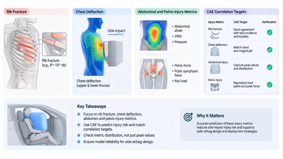
Side impact is fundamentally different from frontal impact in the way the occupant is loaded. In a frontal crash, the restraint system — belt and airbag — has a relatively long ride-down distance and can manage the occupant's kinetic energy progressively. In a side impact, the struck-side occupant sits only a few centimetres from the intruding door trim, and the SAB must absorb energy within a very short stroke. As a result, the injury mechanisms are dominated by direct contact loading of the thorax, abdomen, and pelvis, and the injury criteria used to judge SAB performance are correspondingly different from frontal criteria.
This chapter defines the injury metrics that govern SAB design, explains the physical mechanism behind each, and specifies the CAE correlation targets that a validated side impact model must achieve before it can be used for design decisions.
3.1 Why Side Impact Needs Its Own Criteria
Frontal criteria such as HIC and chest acceleration were developed for belt-loaded, distributed loading. In side impact, the load path is lateral and concentrated: the door trim, armrest, and SAB contact the rib cage over a narrow band. The rib cage is loaded in a direction for which it has less structural stiffness than the sternum-to-spine direction, so rib fracture occurs at lower force levels. Abdominal and pelvic loading also become primary concerns because the SAB and door trim can intrude into these regions. Consequently, side impact regulations and consumer protocols (FMVSS 214, Euro NCAP side impact, and IIHS side impact) rely on deflection-based and force-based criteria rather than acceleration-based ones alone.
3.2 Thoracic Injury Criteria
Rib fracture is the dominant thoracic injury in side impact. It is driven by local rib bending and by the rate of chest compression. In CAE, rib fracture is not directly predicted by a single scalar; instead, it is inferred from chest deflection, deflection rate, and the number of ribs exceeding a strain threshold in a detailed rib model. For lumped-parameter or hybrid models, the Rib Deflection Criterion (RDC) and the Thoracic Trauma Index (TTI) are used.
Chest deflection is the primary measurable quantity. In the ES-2re and SID-IIs crash test dummies, chest deflection is measured by a rib displacement transducer at a specific rib level. The standard acceptance value for the ES-2re in Euro NCAP side impact is a maximum chest deflection of 42 mm for the 50th percentile male, with lower values for the 5th percentile female (SID-IIs). The deflection is not a single number in CAE — it must be extracted at the same rib location and in the same direction as the physical transducer.
Viscous Criterion (VC) captures the rate-dependent behaviour of soft tissue. It is defined as the product of chest compression and the rate of deformation:
VC = (dD(t)/dt) * (D(t) / D_max)

where:
  D(t)     = instantaneous chest deflection (m)
  dD/dt    = deflection rate (m/s)
  D_max    = maximum chest deflection (m)
  VC       = viscous criterion (m/s)
The commonly cited injury threshold for VC is 1.0 m/s for the 50th percentile male, with a 25% risk of severe thoracic injury (AIS 3+). In CAE, VC is computed from the same deflection signal used for chest deflection, so the two criteria are correlated but not redundant — a high-rate, low-deflection event can produce a high VC while staying below the deflection limit.
3.3 Abdominal and Pelvic Injury Metrics
Abdominal injury in side impact is assessed through the Abdominal Peak Force (APF) and, in some protocols, through abdominal deflection. The APF is measured by a load cell in the dummy's abdomen. The Euro NCAP side impact protocol sets a high-performance limit of 1.0 kN and a low-performance limit of 2.5 kN for the ES-2re. In CAE, the APF must be extracted from the contact force between the SAB and the abdominal region, not from the total door force.
Pelvic injury is evaluated using the Pelvic Force (PF) or the Pubic Symphysis Force, depending on the dummy. The ES-2re measures pelvic force via a load cell at the pelvis. The acceptance limit is typically 4.0 kN for the 50th percentile male. Pelvic fracture is a significant concern because it can occur without thoracic injury and is often caused by the door trim or SAB bottom edge loading the iliac crest.
The following table summarises the key criteria and their typical CAE correlation targets for a 50th percentile male ES-2re model in a Euro NCAP side impact configuration.
| Injury Metric | Measurement Location | Physical Limit | CAE Correlation Target |
|---|---|---|---|
| Chest Deflection | Rib 4–6, lateral | 42 mm | ±3 mm of test at peak |
| Viscous Criterion (VC) | Derived from deflection | 1.0 m/s | ±0.15 m/s of test at peak |
| Abdominal Peak Force | Abdominal load cell | 2.5 kN (low perf.) | ±0.3 kN of test at peak |
| Pelvic Force | Pelvic load cell | 4.0 kN | ±0.4 kN of test at peak |
| Rib Fracture (detailed model) | Rib strain | 1% strain threshold | Number of fractured ribs within ±1 of test |
3.4 CAE Correlation Targets and Their Meaning
Correlation targets are not arbitrary tolerances. They are derived from the repeatability of the physical test and the sensitivity of the injury metric to modelling uncertainty. For chest deflection, the test-to-test repeatability of a Euro NCAP side impact is typically ±2 mm, so a CAE target of ±3 mm accounts for both test scatter and modelling error. For VC, the rate term amplifies high-frequency noise, so the tolerance is wider in absolute terms but still tight in relative terms.
It is important to distinguish between peak value correlation and time-history correlation. A model can match the peak chest deflection but miss the timing of the peak by 10 ms, which would mislead SAB deployment timing studies. Therefore, a robust correlation target should include both peak magnitude and the time of peak, as well as the overall shape of the curve. A common practice is to compute the CORA (CORrelation and Analysis) rating for the deflection and force curves, with a target CORA score above 0.8 for the thoracic and abdominal signals.
Practical note: When correlating a side impact model, always check the intrusion profile of the door trim first. If the door trim intrusion does not match the test, the occupant loading will be wrong regardless of how well the SAB is modelled. The SAB itself should be correlated after the door structure is validated.
3.5 From Criteria to Design Decisions
Once the model is correlated, the injury criteria become design targets. For example, if the baseline chest deflection is 45 mm and the target is 42 mm, the designer can adjust SAB venting, inflator output, or bag geometry. The CAE model then predicts the new deflection. The correlation targets ensure that the predicted improvement is trustworthy. Without validated correlation, a predicted 3 mm reduction could be entirely within modelling error.
The following SVG illustrates the relationship between the physical loading path, the measured injury metrics, and the CAE correlation targets for a side impact event.
3.6 Practical Correlation Workflow
A typical correlation workflow for side impact SAB models follows these steps:
- Validate the door structure first. Apply the same barrier impact condition as the physical test and compare door trim intrusion at the occupant contact surface. Target: within 5 mm of test at peak intrusion.
- Validate the dummy positioning. Ensure the ES-2re or SID-IIs model is positioned according to the protocol — seat back angle, H-point, and lateral offset. A 10 mm positioning error can shift chest deflection by 2–3 mm.
- Correlate the SAB deployment. Compare the SAB pressure or contact force history against the test. If the SAB is not instrumented in the test, correlate the occupant response instead.
- Extract injury metrics. Use the same signal processing as the test lab: CFC 600 filter for deflection and force, CFC 180 for acceleration. Apply the same windowing and peak detection.
- Compute CORA or equivalent. For each signal, compute the correlation rating. A score above 0.8 is generally acceptable for design use; above 0.9 is required for regulatory submission.
- Document deviations. If a signal cannot be correlated within target, document the reason — e.g., unknown material properties, unmodelled contact friction — and assess the impact on the design decision.
Common pitfall: Correlating only the peak value while ignoring the time history. A model that matches peak chest deflection but predicts the peak 15 ms early will give misleading guidance on SAB venting timing. Always compare the full curve and the time of peak.
3.7 Summary
Side impact injury criteria are deflection-based and force-based because the loading is direct and concentrated. Chest deflection, VC, abdominal peak force, pelvic force, and rib fracture count form the core metric set. Each has a physical limit and a CAE correlation target that accounts for test repeatability and modelling uncertainty. A validated model must match both peak magnitude and time history, and the correlation must be established in the correct order: door structure, dummy positioning, SAB deployment, then occupant response. With a correlated model, the designer can confidently use CAE to optimise SAB parameters against these criteria.