1. SAB system overview
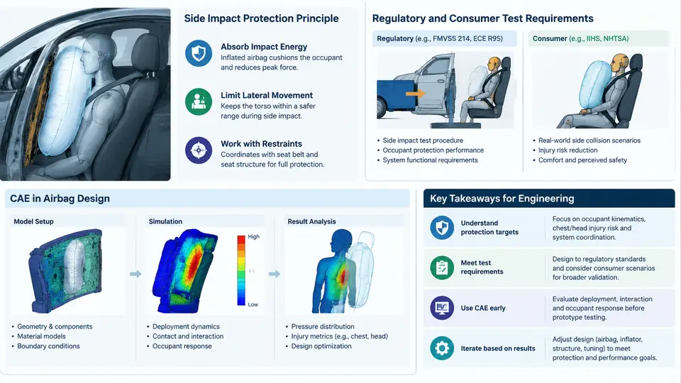
A Side Airbag (SAB) is a pyrotechnic restraint device mounted in the seat back or door trim that deploys laterally between the occupant and the intruding structure during a side impact. Unlike frontal airbags, which have roughly 50–80 ms of crash pulse to work with, SABs must inflate in 10–25 ms because the struck-side occupant sits only 150–300 mm from the door. This short standoff distance is the defining constraint of side airbag design: the bag must be fully pressurized before the occupant's thorax and pelvis contact the door trim, yet it must not deploy with enough force to injure an out-of-position (OOP) occupant.
Side Impact Protection Principles
In a side collision, the struck vehicle has very little crumple zone — typically 100–200 mm of door structure before the occupant compartment is breached. Energy management therefore relies on three sequential mechanisms: the door beam and B-pillar absorb and redirect intrusion energy; the SAB distributes the remaining load over a larger thorax/abdomen area; and the seat structure and belt system restrain the occupant against lateral excursion. The SAB's contribution is primarily load distribution rather than energy absorption — it converts a concentrated door-trim impact into a broad pressure field across the rib cage and pelvis.
Two SAB architectures dominate passenger vehicles. A thorax-only SAB (typically 8–15 L) protects the rib cage and is mounted in the seat backrest side bolster. A thorax-abdomen-pelvis combination SAB (15–25 L) extends lower to cover the pelvis and is common in SUVs and crossovers where the occupant sits higher relative to the door sill. The choice depends on the vehicle's side structure stiffness, the H-point height, and the regulatory test configuration the vehicle must pass.
Regulatory and Consumer Test Requirements
SAB design is driven by three test families: FMVSS 214 (US regulation), UN R95 (European regulation), and consumer programs such as Euro NCAP and C-NCAP. Each imposes different barrier types, impact angles, and injury criteria.
| Test Program | Barrier / Configuration | Impact Speed | Primary Injury Criteria |
|---|---|---|---|
| FMVSS 214 (SID-IIs) | MDB, 27° crab angle | 54 km/h | Rib deflection, abdominal force, pelvic force |
| UN R95 (Euro SID-2) | MDB, perpendicular | 50 km/h | Rib deflection, abdominal force, pubic symphysis force |
| Euro NCAP (AE-MDB) | MDB, 10° angle | 60 km/h | Rib deflection, abdominal force, pelvic force |
| C-NCAP (AE-MDB) | MDB, 10° angle | 50 km/h | Rib deflection, abdominal force, pelvic force |
The critical difference between these tests is the barrier face and the dummy. FMVSS 214 uses the SID-IIs dummy with a 27° crab angle, which produces a more oblique loading path. UN R95 uses the Euro SID-2 dummy with a perpendicular impact. Euro NCAP's AE-MDB barrier is stiffer and heavier than the regulatory barriers, making it the most demanding for SAB coverage. A SAB that passes UN R95 may still fail Euro NCAP if the bag does not extend low enough to protect the pelvis under the higher-energy AE-MDB load.
Beyond regulatory compliance, OOP testing (FMVSS 208 for frontal, but similar principles apply to side) requires that the SAB not cause injury when the occupant is leaning against the door or seat side. This is verified through static deployment tests at -30°C, +23°C, and +85°C, with the dummy positioned at various offsets from the seat. The SAB must deploy without exceeding force limits on the OOP dummy's chest and abdomen.
The Role of CAE in SAB Design
CAE simulation is not a validation step appended to the end of SAB development — it is the primary design tool. A typical SAB development program runs 200–500 CAE iterations before a single physical prototype is built. The simulation chain has four stages:
- Inflator characterization: A tank test (closed-volume pressure-time curve) is converted into a mass flow rate and temperature input for the simulation. The inflator model is calibrated against the tank test at three temperatures.
- Bag folding and deployment: The folded bag geometry is modeled explicitly, and the deployment is simulated using a uniform pressure or gas-flow approach. The bag's unfolding pattern determines whether it contacts the occupant's thorax or slips behind the door trim.
- Occupant restraint simulation: A full vehicle side impact model with the SID-IIs or Euro SID-2 dummy is run. The SAB interacts with the dummy's rib cage, abdomen, and pelvis. Outputs include rib deflection, abdominal force, and pelvic force.
- Design optimization: Parameters such as bag volume, inflator output, vent size, and tether positions are varied to minimize injury criteria while meeting OOP force limits.
The most common CAE failure mode is bag slip: the SAB deploys but slides between the door trim and the occupant's arm, leaving the thorax unprotected. This is detected in simulation as a sudden drop in contact force at the rib location and a corresponding spike in rib deflection. The fix is usually a tether or a change in the bag's mounting angle, which can be evaluated in CAE within hours rather than weeks of physical testing.
System Architecture and Signal Chain
The SAB is part of a larger side restraint system. The signal chain begins with the side impact sensors (accelerometers or pressure sensors in the B-pillar and door), passes through the airbag control unit (ACU), and ends at the inflator. The ACU must decide to deploy within 5–8 ms of impact — a decision window so short that the sensor signal is often still rising when the deployment command is issued. This is why CAE models must include the sensor response and the ACU algorithm, not just the bag and occupant.
The diagram above shows the physical signal chain from sensor to cushion, and the parallel CAE loop that predicts each stage. The red dashed feedback path is the design iteration cycle: if the injury criteria are not met, the bag volume, vent size, tether layout, or mounting angle are adjusted and the simulation is re-run. In practice, a single iteration takes 4–12 hours on a high-performance computing cluster, depending on mesh density and whether the model is a full vehicle or a sled-based subsystem.
For the remainder of this course, we will build a complete SAB CAE workflow: starting from inflator tank test data, through folded bag meshing, occupant positioning, and finally injury criteria evaluation against FMVSS 214 and Euro NCAP targets. The goal is not just to run a simulation, but to understand which design parameters control which injury metrics — and how to make the right change when a simulation fails.