3. Occupant packaging and out-of-position c
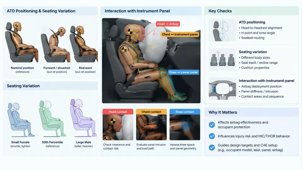
Passenger airbag performance is not determined by the inflator or cushion alone. It is determined by the geometric relationship between the deploying cushion and the occupant at the moment of deployment. This relationship is established long before any simulation runs — it is fixed by the seating package, the instrument panel (IP) surface, the airbag module location and angle, and the range of occupant sizes and postures the vehicle must protect. This chapter examines how occupant packaging defines the boundary conditions for passenger airbag CAE, and how out-of-position (OOP) requirements constrain the design space.
3.1 The Packaging Chain: From H-Point to Cushion Trajectory
Every passenger airbag analysis begins with a reference occupant position. In FMVSS 208 and the corresponding CAE workflow, this is anchored to the H-point (hip point) of the seat, which is established by the SAE J826 HPM (H-point machine) or the manufacturer's design H-point. From the H-point, the ATD (Anthropometric Test Device) is positioned using the standard seating procedure defined in the regulation — for the 50th percentile Hybrid III male, this means a specific torso angle, head position, and knee angle that place the ATD in a repeatable, regulation-compliant posture.
The critical packaging parameters that follow from this are:
- H-point to IP distance — the longitudinal gap between the occupant's hip and the IP surface, which sets the available deployment distance.
- IP surface height and slope — determines where the cushion contacts the IP and how it is redirected toward the occupant.
- Module location and angle — the airbag module is typically mounted in the IP top surface or the front face; its angle relative to the occupant's chest and head defines the primary deployment vector.
- Windshield and header geometry — the cushion interacts with the windshield and roof header, which act as reaction surfaces that shape the final cushion position.
In CAE, these parameters are not abstract. They are explicit coordinates in the model: the ATD's H-point is a node set, the IP surface is a rigid or deformable mesh, and the module is defined by a reference point and a normal vector. A change of 20 mm in module position or 5° in module angle can shift the cushion's contact patch on the occupant's chest by tens of millimeters, which directly affects chest deflection and head acceleration.
3.2 ATD Positioning and Seating Variation
The regulation defines a single nominal ATD position, but real occupants occupy a range. CAE must therefore evaluate a matrix of positions, not a single configuration. The standard approach is to define a seating variation matrix that spans the fore-aft and recline adjustment range of the seat, plus the ATD size variants required by the regulation.
| Parameter | Nominal | Variation Range | CAE Representation |
|---|---|---|---|
| Seat fore-aft position | Design H-point | Full track travel (e.g., ±100 mm) | Translate ATD and seat mesh |
| Seat back angle | 25° from vertical | Design range (e.g., 20°–30°) | Rotate ATD about H-point |
| ATD size | 50th Hybrid III | 5th female, 95th male | Swap ATD model, re-position |
| Head position | Regulation-defined | OOP positions per FMVSS 208 | Prescribed head/torso offsets |
For each combination, the CAE engineer must re-establish the ATD position using the same procedure as the physical test. This is not simply a translation: the ATD's limbs, spine, and head must be re-posed so that the H-point remains at the seat reference point and the torso angle matches the seat back angle. In LS-DYNA or PAM-CRASH, this is typically done with a positioning script or a pre-defined ATD positioning file that applies the correct joint angles and then translates the whole assembly.
3.3 Out-of-Position (OOP) Considerations
OOP refers to occupant positions that are outside the normal seated posture — for example, a child leaning forward, an occupant with their head near the IP, or an occupant with their torso rotated. FMVSS 208 defines specific OOP test positions for the passenger airbag, including:
- Position 1: Head and torso upright, but the occupant is moved forward so the head is near the IP.
- Position 2: Head and torso leaning forward, with the head close to the IP top surface.
- Position 3: Head and torso leaning forward and to the side, with the head near the IP.
- Position 4: Occupant seated normally but with the head turned or tilted.
These positions are defined by specific distances and angles between the ATD and the IP. In CAE, they are implemented by translating and rotating the ATD relative to the IP until the prescribed geometric conditions are met. The simulation then runs the airbag deployment with the ATD in that position, and the injury criteria (HIC, chest deflection, neck injury) are evaluated.
The engineering challenge is that the airbag must deploy safely for both the nominal in-position occupant and the OOP occupant. A cushion that is too aggressive may injure an OOP occupant; a cushion that is too soft may not provide adequate restraint for the in-position occupant. This trade-off is resolved through adaptive venting, tethering, and inflator output modulation, all of which are tuned in CAE.
3.4 Interaction with the Instrument Panel
The IP is not a passive backdrop. It is an active reaction surface that shapes the deploying cushion. The cushion contacts the IP, slides along it, and is redirected toward the occupant. The IP's geometry — its curvature, its stiffness, and its surface friction — determines how much of the cushion's energy is directed toward the occupant versus absorbed by the IP.
In CAE, the IP is typically modeled as a combination of rigid surfaces (for the structural substrate) and deformable elements (for the foam and skin). The contact between the cushion and the IP is defined with a penalty-based contact algorithm, and the friction coefficient is a critical parameter. A typical value for the IP surface is 0.2–0.3, but this must be validated against physical tests.
The following SVG illustrates the packaging relationship between the ATD, the IP, and the deploying cushion, including the key geometric parameters and the OOP positions.
3.5 CAE Workflow for Packaging and OOP Analysis
A typical CAE workflow for passenger airbag packaging and OOP analysis proceeds as follows:
- Build the nominal model. Import the seat, IP, windshield, and ATD meshes. Position the ATD at the design H-point using the regulation seating procedure. Verify that the ATD's head, chest, and knees are at the correct distances from the IP and seat.
- Define the airbag module. Specify the module reference point, the deployment direction (normal vector), and the initial cushion geometry. In LS-DYNA, this is done with the
*AIRBAGkeyword and the*INITIAL_FOAM_REFERENCE_GEOMETRYcard. - Run the nominal in-position simulation. Deploy the airbag and evaluate the occupant response. Check HIC, chest deflection, and neck injury criteria against the targets.
- Generate the OOP matrix. For each OOP position defined by FMVSS 208, translate and rotate the ATD to the prescribed position. Re-run the simulation. Note that the airbag deployment must be triggered at the same time as the in-position case, but the occupant is already close to the IP.
- Evaluate and iterate. If any OOP case exceeds the injury criteria, adjust the cushion design — for example, by adding a tether to reduce the cushion's forward projection, or by increasing the vent size to reduce internal pressure. Re-run both the OOP and in-position cases to ensure the change does not degrade the nominal performance.
3.6 Key Takeaways
- Occupant packaging defines the geometric boundary conditions for passenger airbag CAE. The H-point, IP surface, and module location are the primary parameters.
- ATD positioning must follow the regulation seating procedure, and seating variation must be represented by a matrix of fore-aft, recline, and size combinations.
- OOP positions are defined by specific geometric relationships between the ATD and the IP. They must be simulated with the same airbag deployment timing as the in-position case.
- The IP is an active reaction surface. Its geometry, stiffness, and friction affect the cushion trajectory and must be modeled accurately.
- The design trade-off between in-position restraint and OOP safety is resolved through adaptive venting, tethering, and inflator modulation, all tuned in CAE.
With the packaging and OOP framework established, the next step is to examine how the airbag cushion itself is modeled — its geometry, material properties, and the gas flow that drives deployment. That is the subject of the following chapter.