1. PAB system overview
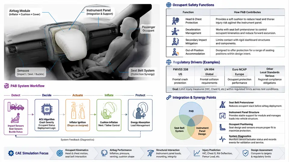
The Passenger Airbag (PAB) is the primary frontal-impact energy-management device for the front outboard passenger seating position. Unlike the driver airbag, which is packaged inside a dedicated steering-wheel module with a well-defined reaction surface, the PAB must be packaged behind a styled, customer-visible instrument panel (IP) surface, deploy through a controlled tear seam, and interact with a seat-occupant environment that varies from a rear-facing infant seat to a large adult in a fully reclined posture. This chapter establishes the system-level context that every subsequent design and CAE task depends on: what the PAB is required to do, which regulations and consumer protocols define those requirements, and how the PAB module, IP structure, and the rest of the restraint system must be co-designed.
Occupant Safety Function of the PAB
In a frontal crash, the vehicle decelerates rapidly while the unbelted or belted occupant continues forward under inertia. The PAB's job is to intervene in the narrow window between occupant kinematics and hard contact with the IP, providing a compliant, energy-absorbing surface that distributes restraint loads over the head, neck, and torso rather than concentrating them at a single contact point. Three functions are typically distinguished:
- Kinematic coupling: the deploying cushion must reach the occupant early enough to "catch" the head and chest before they strike rigid IP or structural components.
- Load distribution: internal tethers, seams, and venting control cushion pressure so that head and chest accelerations stay within injury thresholds.
- Out-of-position (OOP) mitigation: for occupants close to the IP, the deployment energy itself must be limited so that the inflating cushion does not cause injury.
These functions are quantified through injury criteria such as HIC15 (head injury criterion), 3 ms chest acceleration clip, and Nij (neck injury). A typical design target for a belted 50th-percentile male in a 56 km/h full-frontal rigid-barrier test is HIC15 ≤ 700 and chest deflection ≤ 50 mm, though the exact targets are set by the OEM's internal requirements and the applicable regulatory or consumer protocol.
Regulatory and Consumer-Protocol Drivers
The PAB design space is bounded by a set of mandatory and voluntary requirements. The most influential are summarized below.
| Requirement | Scope | Key PAB-relevant implication |
|---|---|---|
| FMVSS 208 | US frontal occupant protection | Unbelted and belted barrier tests; OOP tests with child and small-female surrogates; suppression/deactivation logic for rear-facing child seats. |
| ECE R94 / R137 | UN frontal impact | Belted 40% offset deformable barrier; airbag must not increase injury for belted occupants. |
| FMVSS 201 / ECE R21 | Interior head impact | IP surface and airbag cover must meet head-impact deceleration limits when struck by a free-motion headform. |
| US NCAP / Euro NCAP | Consumer rating | Higher-severity frontal and mobile progressive deformable barrier tests; OOP and child-presence evaluation. |
| FMVSS 302 / ISO 3795 | Flammability | Cushion fabric and IP materials must meet burn-rate limits. |
Two consequences deserve emphasis. First, FMVSS 208's OOP requirements mean the PAB cannot be designed purely for the 50th-percentile belted occupant; the inflator output, cushion volume, and venting must be tuned so that a 1-year-old CRS or a small female positioned close to the IP is not injured by deployment. Second, the occupant-classification system (OCS) in the passenger seat must be able to suppress or deactivate the PAB when a rear-facing child seat is detected, which couples the PAB to the seat sensor and the airbag control unit (ACU) calibration.
Integration with the Instrument Panel
The PAB module is a structural and cosmetic subsystem of the IP. Its integration constraints are severe because the IP is simultaneously a Class-A surface, a structural carrier for HVAC and electronics, and the reaction surface for the deploying cushion. The main interfaces are:
- Chute and reaction surface: the IP substrate must provide a rigid chute that guides the cushion toward the occupant and reacts the deployment loads without excessive deflection.
- Tear seam: a laser or knife score in the IP skin/substrate defines the door opening. Seam geometry controls opening force and door trajectory; a weak seam opens too early and loses pressure, a strong seam delays deployment and can cause cover fragmentation.
- Module mounting: the PAB housing is bolted to the IP cross-car beam or a dedicated bracket. Mounting stiffness directly affects cushion trajectory and the repeatability of deployment.
- Thermal and NVH: the inflator generates a short, high-temperature gas pulse; adjacent materials must survive without melting or emitting debris.
Integration with the Restraint System
The PAB does not act alone. Its performance is coupled to the seat belt, the seat structure, the ACU calibration, and the OCS. Key interactions include:
- Belt–airbag interaction: a load-limited retractor and pretensioner control how much the occupant moves forward before the airbag is fully inflated. If the belt allows too much excursion, the occupant may "submarine" under the cushion; if too little, the airbag may deploy into an already-restrained occupant.
- ACU calibration: the crash pulse, safing sensor logic, and deployment time are tuned together with the PAB inflator output. A change in inflator output typically requires re-validation of the ACU deployment threshold.
- OCS and suppression: the passenger seat weight and position sensors feed the ACU, which decides whether to deploy, suppress, or deploy at reduced output. This logic must be validated against FMVSS 208 OOP and child-seat scenarios.
System-Level Data Flow and Decision Logic
The diagram below summarizes how the PAB sits within the restraint system: sensor inputs feed the ACU, which commands the inflator; the inflator fills the cushion, which interacts with the IP tear seam and the occupant. The same figure highlights the feedback paths — OOP sensing and OCS — that modify the deployment decision.
Practical Design Considerations and a Worked Example
To make the integration concrete, consider a mid-size SUV passenger-side PAB with the following assumed concept parameters (these are illustrative, not measured results):
- Inflator: hybrid, 2-stage, peak pressure ~ 220 kPa at 25 ms in a 60 L tank test.
- Cushion: 120 L nominal volume, two side tethers, two 25 mm vents.
- IP tear seam: laser-scored, residual wall thickness 0.6 mm, U-shaped door.
- Target deployment: cushion fully inflated by 28 ms after impact at 56 km/h.
A first-pass CAE check would run a full-frontal rigid-barrier simulation with a belted 50th-percentile Hybrid III occupant. The engineer observes the head contact location, chest deflection, and cushion pressure. If the head contacts the IP above the cushion top edge, the chute angle or cushion height must be adjusted. If chest deflection exceeds the target, the vent area or tether length is modified to soften the cushion. If the tear seam opens late (visible as a pressure spike before cushion expansion), the seam residual thickness is reduced or the door geometry is revised.
Key Takeaways
- The PAB is a system-level device whose performance depends on the IP structure, the seat belt, the ACU, and the OCS — not on the module alone.
- FMVSS 208, ECE R94/R137, and consumer protocols define the test matrix; OOP and child-seat suppression are first-class design constraints.
- IP integration is dominated by chute geometry, tear-seam design, and mounting stiffness; these are the primary levers for trajectory and opening behavior.
- CAE simulation is the tool that connects these parameters to occupant injury criteria, and it must be run with the full restraint system, not the PAB in isolation.