3. Design requirements
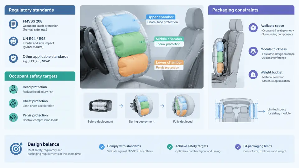
Multi-chamber airbags are not designed in a vacuum. Every geometry decision, fabric selection, and inflator sizing choice is bounded by three interacting requirement sets: the regulatory standards the vehicle must pass, the occupant safety targets the OEM commits to beyond regulation, and the physical packaging envelope available in the steering wheel, instrument panel, seat, or roof rail. These three constraints frequently conflict, and the design engineer's job is to find a feasible operating point rather than to optimize any single one.
Regulatory Standards as Hard Constraints
In the United States, FMVSS 208 governs frontal occupant protection. For a driver-side airbag, the relevant test matrix includes a 50th-percentile male dummy in a 56 km/h (35 mph) full-frontal rigid barrier test, plus unbelted and belted variants, and out-of-position (OOP) tests such as the 5th-percentile female and 3-year-old child surrogate positioned close to the module. The pass criteria are injury assessment reference values (IARVs): HIC15 ≤ 700, chest deflection ≤ 63 mm for the 50th-percentile male, and neck injury criteria limits. FMVSS 208 also imposes a static deployment test at both hot (+85 °C) and cold (−35 °C) inflator conditions, which directly constrains the gas generant load and the chamber fill timing.
In Europe, UN Regulation No. 94 (ECE R94) defines the frontal impact test at 56 km/h with a 40% offset deformable barrier, and UN R137 addresses airbag-specific requirements. China's GB 11551 and the C-NCAP management rules add a 64 km/h offset test. The key engineering consequence is that a multi-chamber airbag must satisfy multiple load cases with different intrusion profiles, which is precisely why chambered architectures are attractive: the upper chamber can be tuned for head/neck, the lower chamber for chest, and the two can be decoupled in timing.
Occupant Safety Targets Beyond Regulation
OEMs typically set internal targets 15–30% below the regulatory IARV to create margin for production variation, aging, and real-world crash diversity. A representative target set for a driver-side multi-chamber airbag might be:
| Metric | Regulatory limit | Internal target | Design driver |
|---|---|---|---|
| HIC15 | 700 | ≤ 550 | Upper chamber pressure and venting |
| Chest deflection (50th male) | 63 mm | ≤ 45 mm | Lower chamber stiffness and contact area |
| Neck tension (50th male) | 4.0 kN | ≤ 3.0 kN | Chamber pressure balance, tether geometry |
| Head rotation (BRIC) | Reported | Minimize | Chamber surface friction, seam placement |
These targets are not independent. Increasing upper-chamber pressure to reduce head excursion can raise neck tension; increasing lower-chamber volume to reduce chest deflection can delay full deployment and worsen head contact timing. The multi-chamber architecture exists to break these couplings, but the tuning process remains iterative.
Packaging Constraints
The airbag module must fit within the available envelope in the steering wheel hub, IP, or seat. For a driver-side module, the folded airbag and inflator typically occupy a cylindrical volume of roughly 120–160 mm diameter and 60–90 mm depth. A multi-chamber airbag with internal tethers and separate chambers folds less compactly than a single-chamber bag, so the folded volume is often 10–20% larger for the same inflated volume. This is a direct packaging penalty that must be traded against performance.
Key packaging parameters include:
- Module depth: limited by steering wheel hub or IP surface to structural member distance.
- Folded diameter: constrained by the retainer ring and cover tear seam geometry.
- Inflator envelope: the gas generator or hybrid inflator must fit concentrically or offset within the module.
- Tether routing: internal tethers must not create fold-induced stress concentrations that cause seam failure during deployment.
Packaging also affects deployment kinematics. A bag folded too tightly may not unfold symmetrically, causing the upper and lower chambers to inflate out of sequence. This is why fold pattern development and chamber timing are co-designed rather than sequential.
Integrating the Three Requirement Sets
The practical design workflow begins with a packaging envelope from the vehicle package team, a regulatory test matrix from the safety team, and internal targets from the occupant protection group. The engineer then proposes a chamber architecture, estimates inflated volumes and pressures, and checks whether the folded volume fits. If not, the trade space includes reducing chamber volume, changing fabric permeability, adjusting inflator output, or modifying the fold pattern.
A useful early-stage check is the volume budget: total inflated volume must be achievable within the folded envelope at the target fold density. For a typical driver-side multi-chamber bag, inflated volume might be 60–75 L for the upper chamber and 25–35 L for the lower chamber, with a folded density of 0.35–0.45 g/cm³. If the calculated folded volume exceeds the envelope, the design must be revised before any simulation is run.
Visualizing the Requirement Interaction
The following diagram shows how the three requirement sets constrain the design space and where conflicts typically arise. The central design point must satisfy all three simultaneously; the arrows indicate the direction of increasing severity for each constraint.
From Requirements to Design Parameters
Translating these requirements into concrete design parameters requires a structured approach. The following table summarizes how each requirement maps to a controllable design variable and a typical verification method.
| Requirement | Design variable | Verification method |
|---|---|---|
| HIC15 ≤ 550 | Upper chamber pressure, vent size, fabric permeability | Sled test + CAE correlation |
| Chest deflection ≤ 45 mm | Lower chamber volume, contact area, tether length | Sled test with chest band |
| Neck tension ≤ 3.0 kN | Chamber pressure ratio, upper tether geometry | Sled test + dummy neck load cell |
| OOP pass at −35 °C | Inflator output, chamber fill sequence, vent area | Static deployment at cold temperature |
| Folded volume ≤ envelope | Fold pattern, chamber nesting, fabric thickness | Physical fold trial + CT scan |
Note that the verification methods are not interchangeable. A CAE model that predicts HIC within 10% of sled test is useful for design iteration, but the regulatory submission requires physical test data. Similarly, a fold trial that fits the envelope does not guarantee symmetric deployment; high-speed video at 1000+ fps is needed to confirm chamber inflation sequence.
Typical Failure Modes and Troubleshooting
When a multi-chamber airbag fails to meet requirements, the symptoms often point to a specific constraint violation:
- High HIC with acceptable chest deflection: Upper chamber pressure too low or venting too aggressive. Check upper chamber fill time and seam integrity.
- High chest deflection with acceptable HIC: Lower chamber too soft or contact area too small. Check lower chamber volume and tether length.
- OOP failure at cold temperature: Inflator output insufficient at −35 °C. Check gas generant temperature sensitivity and chamber fill sequence.
- Asymmetric deployment: Fold pattern creates uneven chamber inflation. Check tether routing and fold symmetry.
- Folded volume exceeds envelope: Chamber nesting inefficient. Check fold pattern and fabric thickness.
Each symptom maps to a specific design variable, and the troubleshooting process is iterative: change one variable, re-run the relevant test or simulation, and check whether the symptom resolves without creating a new violation elsewhere.
Summary
Design requirements for multi-chamber airbags are defined by three interacting constraint sets: regulatory standards (FMVSS 208, ECE R94, GB 11551) that set hard pass/fail gates; occupant safety targets that provide 15–30% margin below regulation; and packaging constraints that limit folded volume, module depth, and tether routing. The feasible design point must satisfy all three simultaneously, and conflicts between them—such as higher pressure improving HIC but worsening neck tension—are resolved through iterative tuning of chamber volumes, pressures, venting, and fold patterns. The next chapter examines how these requirements translate into specific chamber architecture decisions.