1. Multi-chamber airbag systems
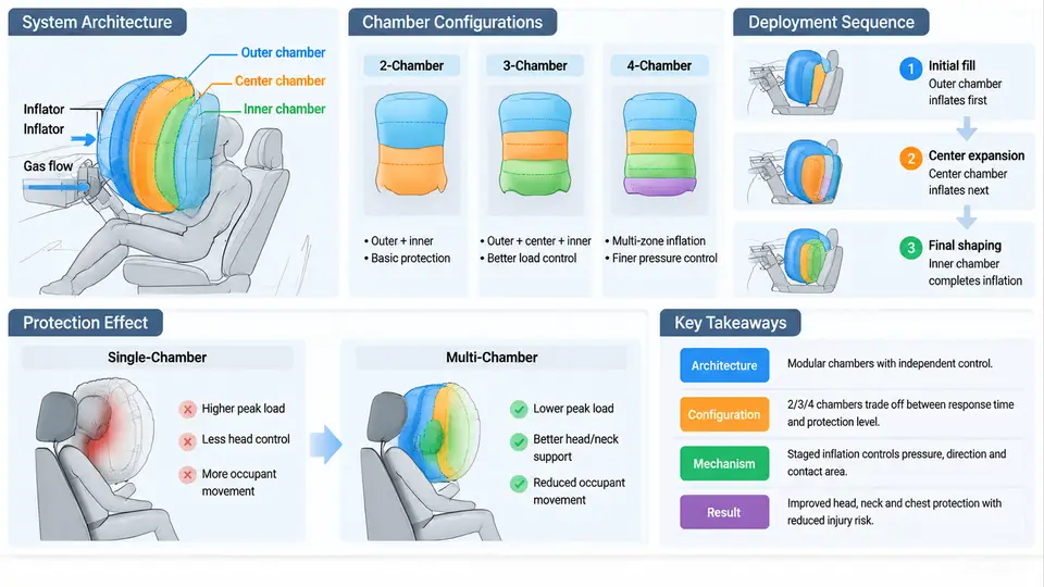
A conventional single-chamber frontal airbag is essentially a single pressure vessel with one inflation source and one vent path. Once the inflator fires, the bag's internal pressure, volume, and restraint force are coupled: increasing pressure to catch a heavy occupant also increases the force applied to a small one. Multi-chamber airbag systems break this coupling by dividing the cushion into two or more volumes that can be pressurized, vented, and loaded independently. This chapter establishes the architectural vocabulary, the principal chamber configurations, and the physical mechanisms through which multiple chambers improve occupant protection. It is the foundation for the modeling and simulation work in the chapters that follow.
Why a Single Volume Is a Compromise
During a frontal impact, the restraint force an airbag applies to the occupant is approximately the product of the internal gauge pressure and the contact area, minus the force carried by the vent flow. For a fixed inflator output, the peak pressure depends on how quickly the cushion volume grows and how much gas escapes through the vents. A 5th-percentile female occupant and a 95th-percentile male occupant reach the cushion at different times, with different kinetic energy, and load different contact areas. A single chamber must therefore be tuned to a statistical compromise, and the tuning is usually biased toward the heavier, higher-energy case because bottoming-out (occupant striking the steering wheel or instrument panel through a fully compressed bag) is the more severe failure mode.
Multi-chamber architecture attacks this compromise directly. By separating the gas volume that first receives the occupant from the volume that provides the final reaction force, the designer can shape the pressure–time and force–deflection history rather than accept a single curve.
Architectural Building Blocks
Every multi-chamber system can be described by four architectural decisions:
- Chamber count and topology. Two-chamber (dual) cushions are the most common; three- and four-chamber cushions appear in side airbags, knee bolsters, and some front-passenger designs.
- Gas routing. A single inflator can feed all chambers through internal passages, or separate inflators (or a dual-stage inflator with two propellant charges) can feed different chambers.
- Inter-chamber communication. Chambers may be sealed from one another, connected by fixed orifices, or separated by a fabric membrane that ruptures or stretches at a calibrated pressure.
- Venting strategy. Venting can be external (to atmosphere), internal (chamber-to-chamber), or active (a tether or flap released by a pyrotechnic or solenoid actuator).
These four decisions are not independent. A sealed two-chamber cushion with a single inflator, for example, requires an internal orifice to distribute gas, and that orifice becomes the dominant tuning parameter for the pressure split between chambers.
Principal Chamber Configurations
Series (tandem) chambers. The occupant-facing chamber is inflated first and acts as a soft "catching" volume; behind it, a second chamber provides the reaction force. Gas flows from the rear chamber to the front chamber through a calibrated orifice or a set of fabric pores. The front chamber pressure rises slowly, which lowers the initial force on the occupant, while the rear chamber remains at higher pressure to prevent bottoming-out. This is the classic architecture for passenger-side airbags, where the occupant is far from the module and the cushion must span a large distance.
Parallel chambers. Two or more chambers sit side by side and are loaded simultaneously. This configuration is typical of side-impact airbags, where a thorax chamber and a pelvis chamber must be tuned to different body regions with different injury tolerances. The chambers share a common inflator but have separate vent paths, so the pelvis chamber can be stiffer than the thorax chamber.
Concentric (nested) chambers. An inner chamber is surrounded by an outer chamber. The inner chamber is pressurized first and provides a firm core; the outer chamber is a lower-pressure envelope that distributes load over a larger contact area. This is used in some knee airbags and in advanced driver airbags to reduce concentrated loading on the sternum.
Segmented (multi-cell) cushions. The cushion is divided into many small cells by internal tethers or seams. Each cell behaves as a small chamber, and the overall pressure distribution is smoothed. This is common in curtain airbags, where the cushion must cover a large window area without a single large volume that would be slow to inflate.
Terminology note. In this course, "chamber" refers to a distinct gas volume separated by a physical boundary (fabric, membrane, or seam). "Cell" refers to a subdivision within a chamber created by tethers that do not fully seal. The distinction matters when writing the gas-flow equations in later chapters.
Occupant Protection Mechanisms
The protection benefit of multiple chambers comes from four mechanisms, each of which can be traced to a specific physical effect.
1. Pressure staging. Because the front chamber fills first and the rear chamber fills later (or vice versa, depending on the design), the pressure–time history seen by the occupant is no longer a single peak. A typical dual-chamber passenger airbag shows an initial low-pressure plateau as the front chamber contacts the occupant, followed by a rise as the rear chamber is compressed. This reduces the initial force spike that causes rib deflection and head rotational acceleration.
2. Load distribution. Parallel and concentric chambers allow the contact area to be increased without increasing total gas volume. A larger contact area at the same pressure produces a lower peak pressure on any single body region, which is the primary driver of injury criteria such as chest deflection and viscous criterion (VC).
3. Bottoming-out prevention. The rear or inner chamber acts as a final energy absorber. Even if the front chamber is fully compressed, the rear chamber still has residual volume and pressure to decelerate the occupant. This is the mechanism that allows a dual-chamber bag to be tuned for a small occupant without sacrificing protection for a large one.
4. Adaptive venting. In systems with active vents, the vent path from one chamber can be opened or closed based on occupant size, seat position, or crash severity. A small occupant triggers a larger vent area, reducing pressure; a large occupant triggers a smaller vent area, preserving pressure. This is the mechanism that makes multi-chamber systems genuinely adaptive rather than merely staged.
From Architecture to Simulation Inputs
When this architecture is translated into a simulation model, each chamber becomes a control volume with its own state variables: pressure P_i, volume V_i, temperature T_i, and mass m_i. The connections between chambers are modeled as orifices with a discharge coefficient C_d and an effective area A_eff. The inflator is modeled as a mass-flow source with a prescribed mass-flow rate ṁ(t) and gas temperature. The occupant is modeled as a moving boundary that compresses the front chamber and, through the orifice, indirectly pressurizes the rear chamber.
A representative set of teaching parameters for a dual-chamber passenger airbag is given below. These are illustrative values chosen to make the simulation behavior visible; they are not measured data from a specific production system.
| Parameter | Symbol | Example value | Role in the model |
|---|---|---|---|
| Front chamber volume | V_front |
60 L | Sets initial pressure rise rate |
| Rear chamber volume | V_rear |
40 L | Sets residual reaction force |
| Orifice effective area | A_eff |
1200 mm² | Controls gas transfer rate between chambers |
| Orifice discharge coefficient | C_d |
0.65 | Accounts for real-flow losses |
| External vent area (front) | A_vent |
800 mm² | Controls pressure decay after peak |
| Inflator mass flow (peak) | ṁ_peak |
2.5 kg/s | Sets fill time |
| Gas temperature | T_gas |
800 K | Affects pressure via ideal-gas law |
With these inputs, a lumped-parameter simulation predicts a front-chamber pressure that rises to roughly 180 kPa in about 25 ms, while the rear chamber lags by 8–12 ms and peaks near 220 kPa. The occupant's chest deflection is then computed from the contact force, which is the product of the front-chamber pressure and the contact area. If the simulated chest deflection exceeds the injury threshold (for example, 50 mm for a 50th-percentile male in a 40 km/h frontal impact), the designer increases A_eff to soften the front chamber, or increases V_rear to provide more residual volume.
Common modeling pitfall. Treating the orifice as a simple linear resistance rather than a compressible-flow restriction. At the pressure ratios typical of airbag deployment (rear/front > 1.5), the flow through the orifice is choked, and the mass-flow rate depends on the upstream pressure and temperature, not on the pressure difference alone. Using a linear model will under-predict the initial transfer rate and over-predict the rear-chamber pressure.
What to Verify Before Moving On
Before proceeding to the modeling chapters, confirm that you can do the following:
- Sketch a series, parallel, and concentric chamber configuration and label the gas path, the orifice, and the vent.
- Explain why a dual-chamber bag can be tuned for a small occupant without sacrificing bottoming-out protection for a large one.
- Identify which architectural lever (chamber count, gas routing, orifice size, vent strategy) controls each of the four protection mechanisms.
- Given a pressure–time curve from a simulation, determine whether the front chamber is filling too fast or too slowly, and propose a parameter change.
The next chapter builds on this vocabulary by deriving the control-volume equations that govern each chamber and the orifice flow relations that couple them.