3. Occupant packaging and knee airbag inter
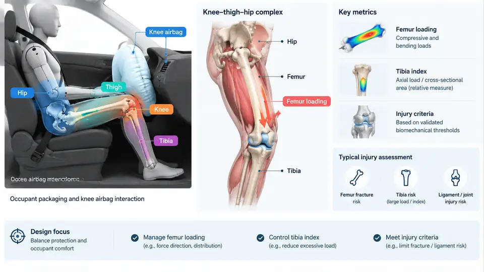
The knee airbag (KAB) is not a standalone restraint; it is the lower-extremity interface between the occupant and the instrument panel (IP) or knee bolster. Its design is therefore governed by occupant packaging — the geometric relationship between the seated occupant's knee-thigh-hip (KTH) complex and the interior surfaces — and by the injury criteria that translate femur and tibia loading into pass/fail targets. This chapter establishes the anatomical, kinematic, and regulatory framework that all subsequent KAB modeling and validation work depends on.
The Knee-Thigh-Hip Complex as a Load Path
The KTH complex comprises the patella, distal femur, femoral shaft, femoral neck, acetabulum, and pelvis. In a frontal impact, the occupant's lower extremities are restrained primarily by the toe pan and floor, while the knees are free to translate forward until they contact the IP or knee bolster. The femur then acts as a load-bearing column: impact force enters at the knee, travels proximally along the femoral shaft, and is reacted at the hip joint and pelvis through the seat belt and seat structure.
Two failure modes dominate. First, femoral shaft fracture, driven by axial compression and bending, typically occurs at the mid-shaft and is quantified by the femur force criterion. Second, hip joint injury — acetabular fracture or posterior hip dislocation — results from force transmitted through the femoral neck into the pelvis. The KAB's role is to distribute the knee impact load over a larger area and to manage the timing of knee engagement relative to pelvis motion, reducing peak femoral force and hip loading.
Occupant Packaging Parameters
Packaging defines the initial conditions for every KAB simulation. The critical parameters are:
- Knee-to-IP clearance (knee gap): the free travel distance before knee contact. Typical mid-size sedan values range from 80–150 mm at the 50th percentile male H-point.
- Knee bolster stiffness: the force-deflection characteristic of the IP substrate and any energy-absorbing insert.
- H-point height and seat track position: determine knee height relative to the bolster and the angle of femoral loading.
- Seat belt geometry: lap belt anchorage and pretensioner behavior influence pelvis restraint and thus relative knee-to-pelvis motion.
- KAB module location and deployment trajectory: where the airbag emerges and how it fills the knee gap.
These parameters are not independent. Increasing knee gap delays contact but allows greater knee velocity at impact; a stiffer bolster reduces travel but raises peak force. The KAB must be tuned to the specific packaging envelope, which is why a single KAB design cannot be carried across vehicle platforms without re-validation.
Injury Criteria and Design Targets
Three criteria dominate KAB design targets in frontal impact:
| Criterion | Measurement | Typical Design Target | Regulatory Reference |
|---|---|---|---|
| Femur force | Axial compressive force at distal femur (Hybrid III) | ≤ 10 kN per leg (FMVSS 208); ≤ 7.5 kN preferred for KAB tuning | FMVSS 208, ECE R94 |
| Tibia Index (TI) | Combined axial force and bending moment at tibia | ≤ 1.0 (dimensionless) | FMVSS 208, Euro NCAP |
| Knee slider displacement | Post-test knee travel | ≤ 150 mm (varies by OEM) | Internal OEM targets |
The Tibia Index is defined as:
TI = Fz / Fc + Mx / Mc

where:
  Fz = axial compressive force at tibia (N)
  Fc = critical axial force = 35.9 kN (for 50th percentile male)
  Mx = bending moment at tibia (N·m)
  Mc = critical bending moment = 225 N·m
A TI of 1.0 represents the threshold for tibia shaft fracture. In practice, KAB designs target TI ≤ 0.7 to provide margin for variation in occupant size and seating position. The femur force criterion is similarly conservative: while 10 kN is the regulatory limit, KAB tuning typically aims for 6–8 kN to account for production variability and off-nominal seating.
Design note: Femur force and TI are coupled. A KAB that deploys too aggressively reduces knee travel but can spike femoral force. A KAB that deploys too softly allows excessive knee excursion, increasing tibia bending moment as the knee rotates about the hip. The optimal KAB pressure-time curve balances these effects.
KAB Interaction Mechanics
When the KAB deploys, it fills the knee gap and presents a compliant surface to the knee. The interaction proceeds in three phases:
- Deployment and gap filling: the inflator fires, the cushion unfolds, and the bag contacts the knee. Timing is critical — the bag must be fully pressurized before knee contact to avoid "bag slap" and to provide consistent restraint.
- Load distribution: the bag spreads the knee impact force over the bolster area. The bag pressure and venting determine the force-deflection response. A well-tuned KAB produces a plateau force rather than a sharp peak.
- Energy absorption: as the knee compresses the bag against the bolster, the bag vents gas and the bolster deforms. The combined stiffness controls peak femur force and knee travel.
The figure below illustrates the KTH load path and the KAB interaction sequence, showing how packaging parameters and injury criteria connect.
Practical Design Workflow
Translating these criteria into a KAB design follows a defined sequence. The following example uses representative values for a mid-size sedan with a 50th percentile male occupant; actual values must be derived from the specific vehicle package.
Step 1 — Establish the packaging envelope. Measure knee gap, bolster stiffness, and H-point from the CAD package. For this example: knee gap = 120 mm, bolster stiffness = 200 N/mm linear, H-point height = 270 mm.
Step 2 — Define the target force-deflection corridor. Using the femur force target of 7 kN and the available knee travel of 120 mm, the average KAB-plus-bolster stiffness should not exceed 7000 N / 120 mm ≈ 58 N/mm. Since the bolster alone contributes 200 N/mm, the KAB must be significantly softer — typically 20–40 N/mm effective stiffness — to keep the combined response within the corridor.
Step 3 — Tune the inflator and venting. Select an inflator mass flow rate that fills the bag volume within 15–20 ms. Set vent hole area to produce a plateau pressure of 30–50 kPa at full knee engagement. Verify via simulation that the femur force peaks below 7 kN and TI remains below 0.7.
Step 4 — Validate off-nominal positions. Run simulations at 5th percentile female and 95th percentile male H-point positions, plus ±50 mm fore-aft seat track variation. Check that femur force and TI remain within targets. If not, adjust KAB volume or venting rather than bolster stiffness, since bolster changes affect other interior functions.
Common failure symptom: If simulation shows a sharp femur force spike above 10 kN at 10–15 ms, the KAB is likely deploying into the knee before full pressurization (bag slap). Remedy: advance inflator timing by 3–5 ms or increase initial bag volume. If TI exceeds 1.0 despite acceptable femur force, the knee is rotating excessively — increase KAB coverage area or add a knee bolster insert to control tibia bending.
Key Takeaways
- The KTH complex is a load path: knee impact force travels through the femur to the hip and pelvis. KAB design must manage both femoral shaft force and hip joint loading.
- Packaging parameters — knee gap, bolster stiffness, H-point, and belt geometry — define the boundary conditions for KAB tuning. They cannot be treated independently.
- Femur force (≤ 10 kN regulatory, 6–8 kN target) and Tibia Index (≤ 1.0 regulatory, ≤ 0.7 target) are the primary design criteria. They are coupled through knee kinematics.
- KAB interaction proceeds through deployment, load distribution, and energy absorption. The optimal pressure-time curve balances knee travel against peak force.
- Validation must include off-nominal occupant sizes and seating positions; a design that passes only the 50th percentile male is not production-ready.