3. Far-side airbag system architecture
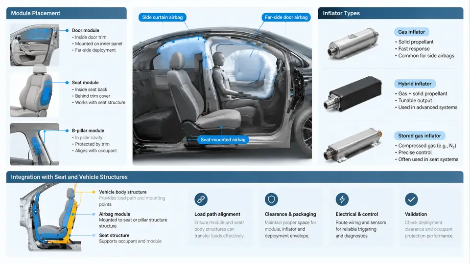
A far-side airbag (FSA) protects occupants from striking one another or interior structures during a lateral impact on the side opposite the occupant. Unlike a frontal airbag, which reacts against a fixed steering wheel or instrument panel, the far-side airbag has no rigid reaction surface. It must create its own reaction force by bridging the gap between the two front seats. This fundamental constraint drives every architectural decision: where the module is mounted, which inflator technology is used, and how the deployment energy is transferred into the seat and vehicle body.
Module Placement Options
Three primary mounting locations dominate current production and development programs. Each represents a different trade-off between packaging space, deployment consistency, and structural load path.
Inboard seat-mounted module. The inflator and cushion are packaged inside the inboard side of the driver or passenger seat backrest, typically within the side bolster foam. The cushion deploys forward and inward, expanding into the center console gap. This is the most common architecture in current vehicles because it follows the same seat-integrated philosophy as side airbags, requires no additional body structure, and deploys identically regardless of seat track position. The primary challenge is that the seat frame must absorb the full reaction force of the deploying cushion, which can exceed 3–5 kN during the initial inflation phase.
Center console-mounted module. The module is housed inside the center console, deploying upward and outward from a concealed tear seam. This location offers a shorter distance to both occupants and can be tuned to cover a wider lateral span. However, it requires the console to be structurally robust enough to serve as a reaction surface, and deployment timing must account for the console lid position and any objects stored in the console bin.
Roof or headliner-mounted module. Less common, this architecture deploys downward from the roof rail area between the two front seats. It provides good coverage for taller occupants and avoids seat structural reinforcement, but packaging space in the headliner is limited, and the downward deployment path can interfere with the occupant's head position during pre-crash maneuvers.
Inflator Types and Selection Criteria
Far-side airbags predominantly use pyrotechnic inflators, though hybrid and stored-gas designs exist for specific applications. The inflator must fill the cushion rapidly—typically within 20–30 ms to reach full pressure—while maintaining a controlled pressure profile that does not cause occupant injury.
| Inflator Type | Typical Application | Output Characteristics | Packaging Consideration |
|---|---|---|---|
| Pyrotechnic (solid propellant) | Inboard seat-mounted FSA | Fast onset, high peak pressure, short duration | Compact, cylindrical or disc shape |
| Hybrid (pyrotechnic + stored gas) | Console-mounted FSA | Moderate onset, sustained pressure, cooler gas | Larger, requires pressure vessel |
| Stored gas (cold gas) | Roof-mounted FSA | Slow onset, low peak pressure, long duration | Bulky, requires high-pressure tank |
Pyrotechnic inflators are the default choice for seat-mounted far-side airbags because they are compact, lightweight, and deliver the rapid pressure rise needed to bridge the seat gap before the occupant's torso displaces laterally. A typical pyrotechnic inflator for FSA produces 60–120 kPa of cushion pressure within 15–25 ms at 23°C ambient. The propellant mass is usually between 15 and 30 grams, depending on cushion volume and target pressure.
Hybrid inflators are used when the cushion volume is larger—for example, in console-mounted systems that must cover both driver and passenger sides. The stored gas component provides a sustained pressure plateau that helps maintain the cushion's shape during the occupant loading phase, while the pyrotechnic charge provides the initial rapid deployment.
Integration with Seat Structure
When the module is mounted in the seat, the seat frame becomes the reaction structure. The deployment force from the inflator is transmitted through the module housing into the seat backrest frame. This requires specific design measures:
- Reinforced backrest frame: The inboard side of the backrest frame is typically upgraded from standard stamped steel to a high-strength steel or aluminum alloy with additional gussets. The frame must withstand the inflator thrust without permanent deformation that could affect seat function.
- Module mounting bracket: A dedicated bracket ties the inflator housing directly to the frame, bypassing the foam and trim. The bracket is designed to fail predictably at a defined load to allow the cushion to deploy through the trim tear seam.
- Trim tear seam: The seat trim cover includes a concealed tear seam on the inboard side. The seam is engineered to open at a specific pressure—typically 200–400 kPa—so that the cushion exits cleanly without tearing the entire cover.
- Foam channel: A molded channel in the seat foam guides the cushion during deployment and prevents the cushion from being trapped between the foam and the frame.
Integration with Vehicle Structure
For console-mounted and roof-mounted far-side airbags, the vehicle body must provide the reaction surface. The center console structure is reinforced with a steel or aluminum inner frame that ties into the floor tunnel. The console lid and bin are designed to remain closed during deployment, or to open in a controlled manner that does not interfere with the cushion path.
In roof-mounted systems, the roof rail and headliner are designed with a deployment channel that directs the cushion downward and inward. The headliner must separate cleanly along a predefined seam, and the roof rail must absorb the reaction force without transferring excessive load to the occupant compartment.
Deployment Sequence and Timing
The far-side airbag deployment sequence is coordinated with the seat belt and side airbag systems. A typical timing diagram for a side impact at 50 km/h with a 50th percentile male occupant:
t = 0 ms    Impact detected by side satellite sensor
t = 5 ms    Airbag control unit (ACU) confirms crash severity
t = 8 ms    FSA inflator receives firing command
t = 10 ms   Inflator begins gas generation
t = 18 ms   Cushion begins to emerge from trim
t = 25 ms   Cushion reaches full deployment (bridges seat gap)
t = 30 ms   Occupant torso contacts cushion
t = 45 ms   Peak occupant loading on cushion
t = 80 ms   Cushion begins to deflate through vent holes
t = 120 ms  Occupant motion controlled, cushion fully deflated
This timing assumes a pyrotechnic inflator at 23°C. At -35°C, the inflator output is reduced, and the deployment time may extend by 5–10 ms. The ACU must compensate by adjusting the firing time or by using a dual-stage inflator that can vary output based on temperature and crash severity.
Practical Verification: Seat-Mounted FSA Deployment Check
To verify that a seat-mounted far-side airbag integrates correctly with the seat structure, engineers perform a static deployment test. The following procedure is representative of a typical validation step:
- Setup: Mount the complete seat assembly, including the FSA module, on a rigid fixture that replicates the vehicle floor and B-pillar mounting points. Install the seat at the mid-track position and set the backrest angle to 25° from vertical.
- Instrumentation: Install a pressure transducer inside the cushion and a high-speed camera (1000 fps) to record the deployment. Place a load cell on the seat frame at the module mounting bracket to measure reaction force.
- Execution: Fire the inflator at 23°C ambient. Record pressure, force, and video for 200 ms.
- Acceptance criteria: Cushion must fully deploy within 30 ms. Peak reaction force at the bracket must not exceed 4.5 kN. The trim tear seam must open cleanly without tearing beyond the seam. The seat frame must show no visible cracks or permanent deformation greater than 2 mm.
- Typical failure symptoms and troubleshooting: If the cushion is trapped by the foam, inspect the foam channel geometry and increase the channel width by 3–5 mm. If the reaction force exceeds the limit, add a gusset to the bracket or increase the frame material thickness. If the tear seam opens prematurely, reduce the seam depth or increase the seam strength by adjusting the stitch pattern.
The architecture described above represents the current state of the art for far-side airbag systems. The key takeaway is that the far-side airbag is not a standalone component—it is a system that depends on the seat frame, the trim, the foam, and the vehicle body working together. Any change to one element requires revalidation of the entire deployment path. Engineers should treat the far-side airbag as an integrated safety system from the earliest packaging phase, not as an add-on module.