3. DAB module components
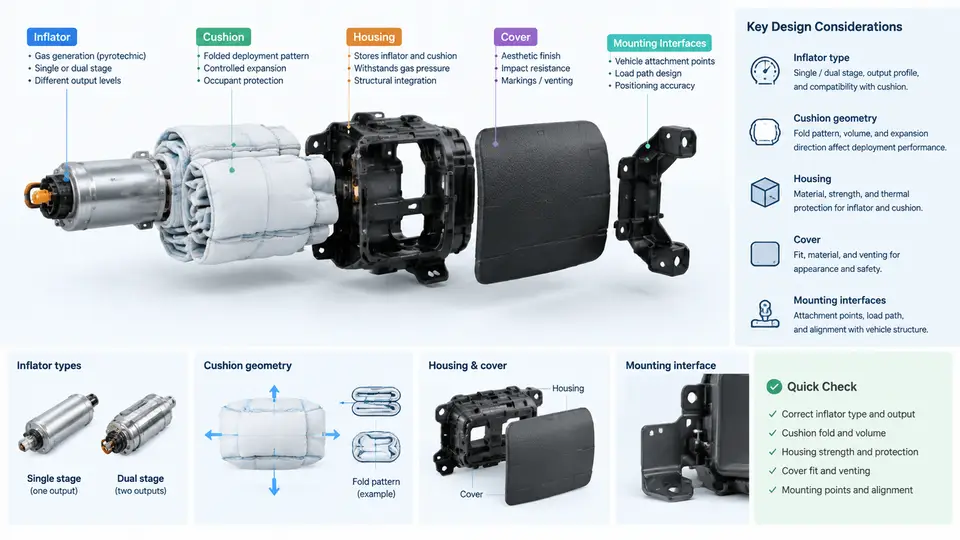
A Driver Airbag (DAB) module is not a single part but a tightly integrated assembly whose behavior under deployment is governed by the interaction of five functional groups: the inflator, the cushion, the housing (also called the retainer or module base), the cover (or deployment door), and the mounting interfaces that tie the module to the steering wheel armature. In CAE terms, each of these groups contributes distinct stiffness, mass, contact, and pressure-volume characteristics. Getting the component definitions right at the modeling stage is what makes the difference between a simulation that predicts the deployment sequence and one that merely produces colorful stress plots.
Inflator Types and Their Modeling Implications
Driver-side inflators fall into three main families. Pyrotechnic (solid-propellant) inflators burn a gas generant to produce inflation gas directly; they are compact and fast but deliver a relatively hot, particulate-laden gas. Hybrid inflators combine a small pyrotechnic charge with a stored compressed gas (typically argon or helium), giving a cooler, cleaner output and a more controllable pressure-time curve. Stored-gas inflators rely primarily on compressed gas released by a pyrotechnic initiator and are less common on the driver side today but still appear in some architectures.
For CAE, the inflator is almost never modeled as a detailed solid. Instead it is represented by a tank (pressure-volume) model or a mass-flow model. The tank model requires three inputs: the inflator's gas mass, the effective gas temperature, and the tank volume. The mass-flow model requires a tabulated mass flow rate versus time curve, usually supplied by the inflator vendor as a .csv or .inc file. A typical driver inflator might deliver on the order of 60–120 g of gas with a peak mass flow near 2–4 kg/s, but these numbers must always come from the vendor's data sheet, not from assumption.
Cushion Geometry
The cushion is a woven fabric bag, usually nylon 6.6, with a defined cut pattern that determines its inflated shape. Driver cushions are typically circular or slightly elliptical, with a diameter in the range of 600–750 mm when fully deployed. The geometry that matters for CAE is not the flat pattern but the folded configuration and the unfolded reference mesh.
Two modeling approaches dominate. The first is the reference geometry method: the cushion is meshed in its fully inflated shape, and the folding is represented by an initial metric mapping or a pre-simulation folding step. The second is the initial folded mesh method, where the folded bag is meshed directly and the inflation is driven purely by the gas flow. The reference geometry method is more stable and is preferred when the deployment kinematics are the primary interest; the folded mesh method is more accurate for the early deployment phase but requires careful contact definition to avoid self-penetration.
Key cushion parameters to document before meshing include fabric areal density (typically 180–240 g/m²), yarn denier, weave pattern, and the seam layout. Seams are usually modeled as either rigid constraints or as stitched connectors with a defined failure force. The vent hole — a critical design feature — must be modeled explicitly, because its diameter and location control the internal pressure decay and therefore the occupant loading.
Housing and Cover
The housing is the structural backbone of the module. It retains the inflator, anchors the cushion, and provides the reaction surface for the cover. It is typically a stamped steel or die-cast aluminum part, and in CAE it is modeled with shell elements (steel) or solid elements (cast aluminum). The housing's stiffness directly affects how much of the inflator's energy is transmitted to the steering wheel versus absorbed by deformation.
The cover is the visible class-A surface and the first component the occupant contacts. It is designed with a tear seam — a thinned region that ruptures at a controlled pressure — and one or more deployment doors that hinge open. The tear seam is the single most important cover feature for CAE. It is modeled either as a reduced-thickness shell region with a failure strain criterion, or as a cohesive zone with a defined fracture energy. A typical tear seam might be 0.6–1.0 mm thick against a nominal cover thickness of 2.5–3.5 mm.
The cover's opening behavior is governed by three parameters: tear seam geometry, door hinge stiffness, and the cover material's strain-rate-dependent properties. Thermoplastic olefin (TPO) and thermoplastic polyurethane (TPU) are common cover materials, and both show significant rate sensitivity. A tensile test at 0.01 s⁻¹ and 100 s⁻¹ will typically show a 30–60% increase in flow stress, and this must be captured in the material card.
Mounting Interfaces
The mounting interface is where the module meets the steering wheel. It consists of the bolt pattern, the locating features, and the electrical connector for the inflator. In CAE, the mounting interface is usually represented by boundary conditions: fixed constraints at the bolt locations, and a rigid or deformable representation of the wheel armature. The choice between rigid and deformable armature representation depends on whether the study is focused on module deployment (rigid is acceptable) or on steering wheel system response (deformable is required).
The electrical connector is rarely modeled explicitly, but its mass and stiffness contribution should be included in the module's total mass and center-of-gravity, which in turn affect the pendulum or sled test correlation.
Putting the Components Together in a CAE Model
A practical DAB module model is built in stages. First, the housing and cover are meshed and assembled with the correct contact definitions — the cover-to-housing interface is typically a tied contact, while the cover-to-cushion interface is a frictionless or low-friction contact. Second, the cushion is positioned in its folded state inside the housing, and the inflator is represented by its tank or mass-flow model. Third, the mounting interface is constrained, and the steering wheel armature is added as either a rigid body or a deformable shell mesh.
A useful verification step before running the full deployment is a static pressure check: apply a uniform internal pressure to the cushion and confirm that the cover tears at the expected pressure and that the cushion does not self-penetrate. If the cover tears too early, the tear seam thickness or failure strain is too low; if it tears too late, the inflator mass flow may be underpredicted or the seam is over-strengthened. This check costs minutes and saves hours of debugging a full transient run.
The component definitions described here form the foundation for the material modeling, contact definition, and validation work in the chapters that follow. Each component's CAE representation must be traceable to a vendor data sheet, a material test, or a documented engineering assumption — because in airbag simulation, an untraceable input is an unverifiable result.