1. DAB system overview
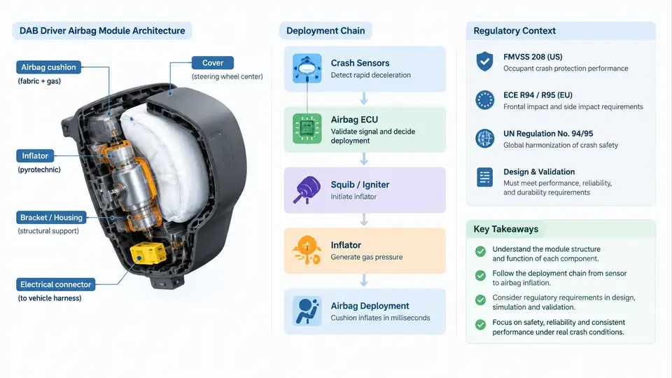
The Driver Airbag (DAB) is the primary occupant restraint device for the vehicle driver and the most safety-critical airbag in the passenger car. Unlike passenger-side or side airbags, the DAB sits directly in front of the driver's chest and head, is mounted on the steering wheel, and must deploy reliably within a very narrow time window while the driver may be leaning, turning, or bracing against the wheel. This chapter establishes the system-level picture that all subsequent CAE work depends on: what the DAB module contains, how the deployment chain propagates from crash sensing to cushion inflation, and which regulatory and consumer-test requirements constrain the design.
1. DAB Module Architecture
A production DAB module is not a single part but an assembly of several functional sub-systems that must be packaged inside the steering wheel hub. The typical architecture includes:
- Inflator (gas generator): A pyrotechnic or hybrid device that produces the inflation gas. Driver-side inflators are usually hybrid or enhanced-pyrotechnic types with a small propellant charge and a compressed-gas reservoir, sized to fill roughly 60–80 L of cushion volume.
- Cushion (bag): A woven fabric envelope, typically nylon 6.6 with a silicone or neoprene coating, folded into a compact package. Driver cushions are usually circular or slightly oval, with a diameter of about 600–700 mm when fully inflated.
- Housing / retainer: A stamped steel or molded plastic structure that holds the folded cushion, the inflator, and the mounting studs, and reacts the deployment loads into the steering wheel armature.
- Cover (deployment door): The visible A-surface on the steering wheel hub. It is designed with a tear seam (H-pattern, X-pattern, or U-pattern) that opens predictably when the cushion inflates.
- Mounting and clock spring interface: The module bolts to the steering wheel armature, and the horn circuit and driver-side squib wiring pass through the clock spring.
Two architectural choices dominate DAB design. In a hard-cover design, the cover is a rigid molded part with a molded-in tear seam. In a soft-cover design, the cover is a flexible TPE or TPU skin over a foam layer, with the tear seam either molded or laser-scored. The choice affects tear-seam opening force, deployment trajectory, and the CAE modeling approach for the cover.
2. Deployment Chain
The deployment chain is the sequence of events from crash detection to full cushion inflation. Understanding this chain is essential because CAE models must reproduce each stage with the correct timing and boundary conditions.
- Crash sensing: Accelerometers in the airbag ECU (typically at the vehicle tunnel or B-pillar) detect deceleration. The ECU applies a crash algorithm (velocity change, energy, or power-based) to discriminate a deployment event from a non-deployment event such as a rough road impact or a low-speed bump.
- Decision and firing command: When the algorithm threshold is met, the ECU sends a firing current to the driver-side squib. Decision time is typically 10–20 ms after impact for a 50 km/h frontal barrier.
- Inflator initiation: The squib ignites the propellant. Gas generation begins within about 1–2 ms, and the inflator reaches peak pressure in roughly 10–20 ms depending on the inflator type.
- Cover opening: Internal pressure rises until the tear seam ruptures. The cover splits and the doors hinge outward. This typically occurs 5–15 ms after inflator initiation.
- Cushion unfolding and inflation: The cushion unfolds from its folded pattern, then inflates to full volume. Full inflation for a driver airbag is typically reached 30–50 ms after impact.
- Occupant interaction and venting: The occupant loads the cushion, and gas vents through fabric porosity and/or vent holes to manage the restraint force. This phase determines injury metrics such as HIC and chest deflection.
The timing budget is tight. For a 50 km/h frontal rigid barrier test, the occupant begins to move forward immediately, and the cushion must be in position before the occupant's head and chest reach the wheel. A typical target is full inflation by 30–40 ms after impact, with the occupant contact occurring shortly after.
T0 = impact; T0+10–20 ms = ECU decision and firing; T0+12–22 ms = inflator initiation; T0+20–35 ms = cover opening; T0+30–50 ms = full cushion inflation; T0+50–80 ms = occupant loading and venting.
3. Regulatory and Consumer-Test Context
DAB design is governed by a combination of government regulations and consumer rating programs. The most relevant are:
| Requirement | Scope | Key implication for DAB |
|---|---|---|
| FMVSS 208 | US frontal occupant protection | Unbelted and belted 50 km/h rigid barrier; out-of-position (OOP) tests; suppression logic for small occupants |
| ECE R94 / R95 | European frontal and side impact | 56 km/h offset deformable barrier; requires compatibility with belt restraint |
| GB 11551 | China frontal impact | 50 km/h rigid barrier; increasingly aligned with global requirements |
| US NCAP / Euro NCAP / C-NCAP | Consumer rating | Star rating driven by HIC, chest deflection, and OOP robustness; drives aggressive inflation and venting tuning |
Two regulatory themes dominate DAB CAE work. First, out-of-position (OOP) requirements (FMVSS 208, and similar provisions in other markets) require that the airbag not cause excessive injury when the occupant is close to or touching the wheel at deployment. This drives the need for inflator output modulation, cushion shape, and venting strategies that reduce peak pressure on the occupant. Second, suppression and low-risk deployment logic requires the ECU to detect small occupants or child seats and either suppress deployment or deploy at reduced output.
4. System-Level View for CAE
From a CAE perspective, the DAB is not analyzed in isolation. The deployment chain couples the vehicle structure, the steering column, the steering wheel, the DAB module, and the occupant. A typical DAB CAE model therefore includes:
- A vehicle body model (or a simplified equivalent) to provide the crash pulse.
- A steering column model with collapsible or energy-absorbing features.
- A steering wheel model with the correct armature stiffness and mass.
- A DAB module model: inflator (mass flow and temperature), cushion (fabric properties, folding pattern), cover (tear seam), and housing.
- An occupant model (Hybrid III 50th, THOR, or human body model) positioned according to the load case.
The simulation must reproduce the timing and pressure history of the inflator, the cover opening, the cushion unfolding, and the occupant interaction. The accuracy of the inflator model and the cushion folding pattern are usually the two largest sources of uncertainty, and both are validated against tank tests and static deployment tests before being used in full vehicle simulations.
5. What This Means for the CAE Engineer
The system overview establishes three practical rules for the rest of this course. First, the DAB is a timing-critical system: every model must be validated against measured inflator pressure, cover opening time, and cushion inflation time before it is used for occupant injury prediction. Second, the DAB is a coupled system: changing the inflator output, the cushion folding pattern, or the cover tear seam will change the occupant response, and these interactions must be captured in the simulation. Third, the regulatory load cases define the simulation matrix: the CAE engineer should build a load-case table that maps each requirement to a model configuration, and track which configurations have been validated and which remain open.
With this system-level picture in place, the next step is to examine the individual components in detail, starting with the inflator and its gas-generation characteristics, which dominate the early phase of the deployment chain.