3. Occupant restraint principles for center
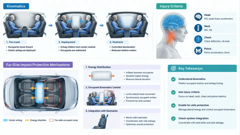
Center airbags address a crash mode that frontal airbags and side curtain airbags were never designed to manage: the far-side impact. In a far-side crash, the occupant sits on the side opposite the impact. The vehicle is struck on the right, but the belted driver on the left is thrown inboard — toward the vehicle centerline — because the restraint forces and the vehicle's lateral acceleration act in opposite directions on the occupant's body. This chapter explains the kinematics of that motion, the injury metrics used to quantify it, and the mechanisms by which a center airbag interrupts the inboard excursion.
Far-Side Kinematics: Why the Occupant Crosses the Centerline
Consider a left-hand-drive vehicle struck on the right side at 50 km/h (a pole or another vehicle). The struck side of the body structure decelerates rapidly; the occupant compartment acquires a lateral velocity toward the left. The driver, restrained by a three-point belt, is coupled to the seat and the B-pillar. The belt's lap and shoulder portions restrain the torso, but the upper torso and head are only loosely coupled. As the vehicle translates leftward, the occupant's head and thorax continue moving rightward relative to the vehicle interior — an inboard excursion. The head then rotates about the neck and can strike the passenger-side occupant, the center console, or the passenger seat structure.
Two kinematic phases matter for restraint design:
- Phase 1 — Torso translation and rotation. The pelvis is held by the lap belt, but the upper torso rotates inboard about the belt's shoulder anchor. The head follows the torso with a lag, producing a lateral neck bending moment.
- Phase 2 — Head excursion and potential contact. The head reaches its maximum inboard displacement (typically 250–400 mm for a belted driver in a 50 km/h far-side sled) and may contact the passenger or interior. The neck is loaded in lateral bending and axial rotation.
The center airbag is deployed from the inboard side of the driver seat (or the center console) during Phase 1, so it is inflated before the head reaches peak excursion. Its purpose is not to absorb the impact of the crash itself, but to arrest the inboard motion of the head and torso before they cross into the passenger's space.
Injury Criteria Relevant to Far-Side Loading
Far-side loading produces injury patterns distinct from frontal or near-side impacts. The relevant criteria are:
| Criterion | Symbol / Limit | What It Measures | Far-Side Relevance |
|---|---|---|---|
| Head Injury Criterion | HIC15 ≤ 700 | Resultant head acceleration over 15 ms | Head-to-head or head-to-interior contact |
| Neck lateral bending moment | My ≤ 57 N·m (reference) | Bending moment about the lateral axis | Primary far-side neck injury mechanism |
| Neck axial rotation | Mz ≤ 30 N·m (reference) | Twisting moment about the vertical axis | Head rotation during inboard excursion |
| Chest deflection | D ≤ 42 mm (reference) | Rib cage compression | Belt loading plus inboard torso motion |
| Thoracic lateral acceleration | ay ≤ 60 g (3 ms clip) | Lateral chest acceleration | Contact with center console or passenger |
These limits are reference values used in CAE target setting; the actual regulatory or consumer-test thresholds depend on the specific protocol (e.g., Euro NCAP far-side sled, FMVSS 226). The key point is that the center airbag must reduce both head excursion and neck bending moment simultaneously — a bag that is too stiff reduces excursion but increases neck moment, while a bag that is too soft allows excessive excursion.
Far-Side Protection Mechanisms
A center airbag protects through three coupled mechanisms:
- Head capture and deceleration. The bag's inboard face contacts the head and applies a distributed lateral force that decelerates the head before it reaches the passenger. The bag's venting and internal pressure determine the deceleration profile.
- Torso support. The bag's lower portion contacts the thorax and abdomen, limiting torso rotation about the belt and reducing the load transferred to the neck.
- Barrier between occupants. The inflated bag occupies the space between driver and passenger, preventing head-to-head contact and distributing any residual contact force.
The design trade-off is captured by the bag's pressure–time curve and vent size. A larger vent reduces peak pressure and neck moment but increases head excursion. A smaller vent does the opposite. CAE simulation is used to sweep these parameters against the injury criteria.
CAE Implementation: Setting Up a Far-Side Sled Model
A typical CAE workflow for center airbag design uses a far-side sled model with a belted Hybrid III 50th percentile male occupant. The key inputs are:
- Impact pulse: lateral acceleration applied to the sled buck, e.g., a 50 km/h far-side pulse with peak acceleration of 25–30 g and duration of 80–100 ms.
- Occupant: Hybrid III 50th male, positioned in the driver seat with a standard three-point belt.
- Center airbag: defined by a
*AIRBAGkeyword (LS-DYNA) or equivalent, with parameters for vent area, initial pressure, and gas mass flow rate. - Contact definitions: head-to-bag, torso-to-bag, and head-to-passenger (if modeling occupant-to-occupant contact).
A representative parameter sweep might vary vent area from 200 mm² to 800 mm² and initial pressure from 1.2 bar to 2.0 bar. The simulation output is a time history of head lateral displacement, neck bending moment, and HIC15. The design target is to keep head excursion below 300 mm while maintaining neck My below 57 N·m.
Vent area = 400 mm², initial pressure = 1.6 bar → head excursion = 280 mm, neck My = 52 N·m, HIC15 = 620.
Vent area = 200 mm², initial pressure = 1.6 bar → head excursion = 240 mm, neck My = 68 N·m (exceeds limit).
Vent area = 600 mm², initial pressure = 1.6 bar → head excursion = 340 mm, neck My = 44 N·m (excursion exceeds target).
Conclusion: the 400 mm² vent provides the best balance for this pulse.
Practical Considerations and Failure Modes
Two common failure modes appear in far-side CAE:
- Bag over-stiffness. If the bag is too stiff, the head rebounds off the bag and the neck moment spikes. Symptom: neck My exceeds 57 N·m even though head excursion is low. Remedy: increase vent area or reduce initial pressure.
- Bag under-inflation or late deployment. If the bag is too soft or deploys too late, the head passes the bag before it is fully inflated. Symptom: head excursion exceeds 300 mm and HIC15 rises. Remedy: increase gas mass flow rate or advance the deployment trigger time.
In practice, the center airbag is tuned together with the seat belt's load limiter and pretensioner. A stronger pretensioner reduces initial torso motion, allowing a softer bag, which in turn reduces neck moment. This coupling is why far-side restraint design is a system-level optimization, not a standalone airbag parameter.