1. CEAB center airbag system overview
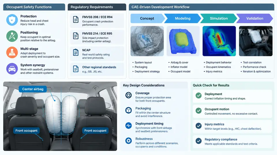
The CEAB (Center Airbag) is a far-side restraint device mounted in the inboard side of the driver or passenger seat, or on the center console, whose primary purpose is to mitigate occupant-to-occupant and occupant-to-interior contact during a lateral impact. Unlike a side airbag that deploys between the occupant and the door, the CEAB deploys into the space between the two front occupants. This distinction drives almost every downstream engineering decision: packaging volume, tether architecture, vent sizing, and the CAE load cases used to validate the design.
Occupant Safety Function
In a far-side impact — a crash in which the struck side is opposite the occupant — the occupant's torso and head are accelerated toward the vehicle centerline. Without restraint, the head can strike the center console, the opposite seat structure, or the other occupant. The CEAB intercepts this motion by inflating a cushion in the gap between the seats, providing a compliant surface that decelerates the head and torso and limits lateral excursion.
The safety function can be decomposed into three measurable contributions:
- Head excursion limitation. The cushion reduces the lateral travel of the head, keeping it within a controlled envelope and lowering the probability of hard contact with the opposite occupant or interior trim.
- Head-to-torso coupling. By supporting the upper torso, the CEAB reduces the differential motion between head and chest, which directly influences neck injury metrics such as Nij.
- Occupant-to-occupant separation. In a two-occupant scenario, the cushion acts as a barrier that prevents direct head-to-head or head-to-shoulder contact.
These functions are not independent. A cushion that is too stiff will limit excursion but may raise head acceleration; a cushion that is too soft will bottom out and allow contact. The design problem is therefore a trade-off, and CAE is the primary tool used to navigate it.
Regulatory and Rating Requirements
Far-side protection is addressed by several regulatory and consumer-rating programs. The most relevant are summarized below. Note that specific thresholds and test configurations vary by region and model year; the values shown are representative and should be confirmed against the current regulation text for the target market.
| Program | Test Configuration | Key Metric | Representative Criterion |
|---|---|---|---|
| FMVSS 226 (ejection mitigation) | Side impact with moving deformable barrier | Head excursion / ejection | Limit head movement through side window |
| Euro NCAP far-side | Oblique pole / MDB, far-side occupant | Head excursion, Nij, chest deflection | Rating-based scoring |
| C-NCAP far-side | Far-side MDB impact | Head excursion, HIC, neck | Rating-based scoring |
| UN R137 / R94 (related) | Frontal and side impact | Restraint system performance | Type-approval thresholds |
Two practical implications follow. First, the CEAB must be validated across a matrix of impact angles, barrier types, and occupant sizes (typically 5th percentile female through 95th percentile male, plus child dummies). Second, because far-side tests often use an oblique or moving barrier, the loading is asymmetric and the occupant kinematics are highly three-dimensional — a condition that is difficult to reproduce with simplified analytical models and that strongly favors explicit finite element simulation.
CAE-Driven Development Workflow
The CEAB development process is iterative and simulation-centric. A typical workflow proceeds through the following stages, each with its own CAE deliverables and exit criteria.
- Concept and packaging study. The available gap between the seats is measured from the CAD assembly. A first-pass cushion volume is estimated from the gap geometry and the target occupant excursion. CAE at this stage uses a simplified cushion model (uniform pressure or low-fidelity fabric) to screen concepts quickly.
- Detailed FE model build. The cushion is meshed with membrane or shell elements, the inflator is represented by a tank-pressure or mass-flow boundary condition, and the seat structure is included as a deformable body. The occupant is positioned using a validated dummy model (e.g., THOR or WorldSID) in the far-side seating position.
- Inflation and deployment simulation. The gas flow from the inflator is applied, and the cushion unfolds. Key outputs are internal pressure, cushion shape at full deployment, and contact force with the occupant.
- Occupant injury simulation. The full crash pulse is applied, and injury metrics are extracted. The design is tuned by adjusting vent area, tether length, cushion volume, and inflator output.
- Design of experiments and optimization. A DOE matrix varies the key parameters, and a response surface is fitted to identify the combination that minimizes injury metrics while satisfying packaging and cost constraints.
- Validation. Physical sled or vehicle tests are run to confirm the CAE predictions. Correlation metrics (e.g., peak pressure, head excursion, Nij) are compared, and the model is updated if necessary.
Cushion volume (deployed)      : 28 L
Inflator mass flow             : 2.8 kg/s peak
Vent area                      : 1200 mm²
Tether length (upper)          : 180 mm
Seat gap (driver-to-passenger) : 420 mm
Target head excursion          : < 180 mm
Target Nij                     : < 1.0
The workflow is not strictly linear. If the injury simulation shows excessive head excursion, the engineer may return to the packaging study to increase cushion volume, or to the inflation simulation to adjust vent timing. CAE compresses this loop from weeks of physical testing to hours of simulation, which is why it is the backbone of modern CEAB development.
System Architecture and Interfaces
The CEAB is not a standalone component. It interfaces with the seat frame, the center console, the inflator module, the wiring harness, and the occupant sensing system. The figure below shows the principal interfaces and the signal path from crash detection to cushion deployment.
The diagram makes the two feedback paths explicit. The physical path runs from sensor to ECU to inflator to cushion to occupant. The engineering path runs from packaging study through simulation and optimization, looping back whenever a target is missed. In practice, the CAE loop executes many times before a single physical prototype is built.
Key Design Parameters and Their CAE Representation
Four parameters dominate CEAB performance, and each has a direct CAE counterpart:
- Cushion volume. Represented by the initial gas volume in the FE model. Larger volume reduces pressure rise rate but increases packaging demand and inflation time.
- Vent area. Modeled as an orifice boundary condition. It controls the pressure decay after peak and therefore the cushion stiffness during occupant contact.
- Tether length and routing. Modeled with seatbelt or membrane elements. Tethers shape the deployed cushion and prevent it from wrapping around the occupant.
- Inflator output. Defined by a mass-flow-versus-time curve or a tank pressure curve. It sets the inflation timing and peak pressure.
What to Watch For
Three failure modes appear repeatedly in CEAB CAE work. First, cushion bottoming: the cushion compresses fully and the occupant contacts the opposite seat or console. The symptom is a sharp rise in head acceleration late in the event; the fix is usually more volume or a stiffer initial inflation. Second, occupant wrapping: the cushion wraps around the head instead of supporting it, often caused by excessive tether length or a vent that opens too early. Third, out-of-position deployment: if the occupant is leaning toward the center console when the airbag fires, the cushion may deploy into the occupant rather than beside them. This is addressed with occupant sensing and deployment thresholds, and it must be evaluated in CAE with the occupant placed in the worst-case out-of-position posture.
Understanding these interactions is the foundation for the detailed modeling, material characterization, and validation work covered in the chapters that follow.