3. Curtain airbag construction
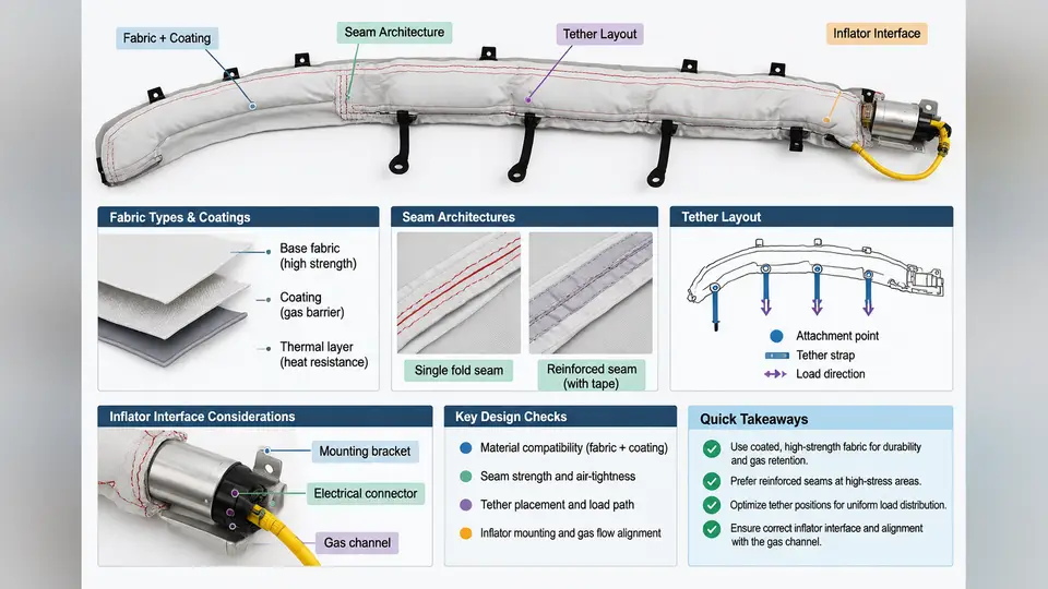
A curtain airbag is not a single bag but a pressure vessel that must deploy in tens of milliseconds, hold a controlled internal pressure for several seconds, and remain anchored to the vehicle body while absorbing occupant energy. Its construction is therefore a system-level compromise among fabric permeability, coating adhesion, seam strength, tether geometry, and inflator output. This section examines each of those elements and how they interact in a real CAB design.
Fabric Types and Their Selection Logic
Curtain airbags are almost universally built from woven polyamide 6.6 (nylon 6.6) yarn, typically in the 470–840 dtex range. The choice between flat-woven and one-piece woven (OPW) fabric is the first major architectural decision.
Flat-woven fabric is cut and sewn into the cushion shape. It offers design flexibility, lower tooling cost, and easy integration of complex outlines, but every cut edge introduces a seam that must be sealed or reinforced. OPW fabric, by contrast, is woven on a Jacquard loom so that the front and rear panels are joined by interwoven yarns along the cushion perimeter and internal chamber boundaries. This eliminates most sewn seams, reduces leak paths, and improves repeatability. The trade-off is higher loom cost and less freedom to change the outline without re-programming the weave.
For a typical side-curtain application, a 470 dtex OPW fabric with a silicone coating on the occupant-facing side and an uncoated or lightly coated body-facing side is common. The uncoated side allows the folded cushion to slide during deployment, while the coated side controls permeability.
Coatings and Permeability Control
Coating is the primary lever for controlling gas retention. Three families dominate:
- Silicone coatings — applied at 20–60 g/m², they provide excellent heat resistance and stable permeability across temperature. They are the default for most OPW curtains.
- Polyurethane (PU) coatings — lower cost, good flexibility, but more sensitive to hydrolysis and heat aging. Used where cost pressure is high and the inflator is a cold-gas type.
- Uncoated / low-permeability weaves — rely on tight weave construction and calendering. They are lightweight and cheap but leak faster, so they suit only short-duration or low-pressure applications.
Permeability is specified as a volumetric leak rate at a reference pressure, for example < 5 L/min at 50 kPa differential. In practice, the CAE engineer should treat coating weight and permeability as a calibrated pair: increasing coating weight reduces leak rate but adds mass and stiffness, which in turn affects foldability and deployment timing.
Seam Architectures
Seams are the weakest link in any sewn cushion. Three architectures are used in CABs:
| Seam Type | Construction | Typical Use | Key Risk |
|---|---|---|---|
| Sewn seam | Lockstitch or chainstitch, 2–4 rows | Flat-woven cushions, tether attachment | Yarn slippage, needle holes leaking |
| OPW interwoven seam | Woven junction, no thread | OPW chamber boundaries | Weave density variation, local thinning |
| Seam seal / tape | Silicone tape or hot-melt film over sewn seam | High-pressure chambers | Adhesive failure at temperature extremes |
For a sewn seam, the stitch density (stitches per 100 mm), thread tex, and needle size must be specified together. A common production specification is a 3-row lockstitch with 40–50 stitches per 100 mm using a 235 dtex bonded nylon thread. The seam must be qualified by a seam tensile test and a seam leakage test at the maximum operating pressure.
Tether Layouts
Tethers control the deployed shape and the cushion's stand-off from the occupant. In a curtain airbag, tethers serve three functions: they limit the outward travel of the cushion, they create the characteristic "sail" shape that covers the window, and they transfer load from the cushion to the body anchor points.
A typical layout includes:
- Perimeter tether — runs along the top edge, anchoring the cushion to the roof rail.
- Vertical tethers — divide the cushion into chambers and control inflation sequencing.
- Diagonal tethers — stabilize the lower edge and prevent the cushion from flapping inward.
Tether attachment points are high-stress locations. In CAE, they are modeled as constrained nodes or as beam elements with calibrated stiffness. The tether length tolerance directly affects the deployed gap between the cushion and the occupant; a 10 mm length error can change the head-to-cushion contact timing by several milliseconds.
Inflator Interface Considerations
The inflator interface is where the gas generator meets the cushion. Key parameters include:
- Inflator type — hybrid, pyrotechnic, or stored-gas. Each has a different mass flow rate and gas temperature profile.
- Mounting orientation — the inflator is usually mounted at the rear of the curtain, with the gas outlet directed into a diffuser or directly into the cushion inlet.
- Sealing — a metal or plastic collar clamps the cushion inlet to the inflator outlet. The clamp force and the cushion inlet diameter must be matched to prevent blow-by.
- Thermal protection — the first 100 mm of the cushion near the inflator must withstand gas temperatures above 1000 °C for a few milliseconds. A heat shield or a thicker coating is often required.
In CAE, the inflator is represented by a tank test pressure–time curve or a mass flow rate curve. The curve is applied to a set of inlet nodes, and the cushion pressure is computed from the ideal gas law with a discharge coefficient. The interface geometry — inlet diameter, diffuser shape, and clamp location — determines the effective discharge coefficient and must be calibrated against a physical test.
Putting It Together: A Design Example
Consider a mid-size SUV side curtain covering the first and second rows. The cushion is 1800 mm long, 600 mm tall, and divided into four chambers. The inflator is a hybrid unit mounted at the C-pillar, delivering a peak pressure of 250 kPa within 15 ms.
The fabric is 470 dtex OPW nylon 6.6 with a 30 g/m² silicone coating on the occupant-facing side. The chamber boundaries are interwoven, and the perimeter is finished with a 3-row lockstitch seam sealed with silicone tape. Vertical tethers are placed at 400 mm intervals, and a diagonal tether runs from the lower front corner to the upper rear anchor.
In CAE, the cushion is meshed with membrane elements (Fabric material model) and the tethers with seatbelt elements. The inflator is represented by a mass flow rate curve derived from a tank test. The simulation predicts a maximum cushion pressure of 230 kPa and a deployment time of 22 ms to full coverage. The seam stress at the perimeter is checked against the seam tensile test data; a safety factor of 1.5 is required.
Key Takeaways
- Fabric type (flat-woven vs. OPW) determines seam count and leak paths; OPW is preferred for high-pressure curtains.
- Coating weight and permeability must be specified together with the reference pressure and the coated side.
- Seam architecture must be qualified by both tensile and leakage tests at maximum operating pressure.
- Tether layout controls deployed shape and occupant stand-off; length tolerances directly affect CAE correlation.
- The inflator interface — clamp, diffuser, and heat shield — must be calibrated against physical test data before it is used in simulation.