1. CAB system overview
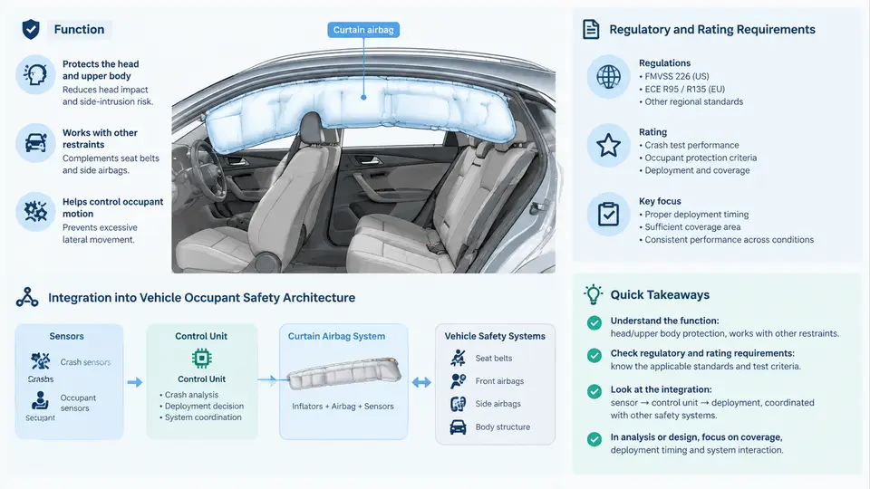
A Curtain Airbag (CAB) is a roof-rail-mounted inflatable restraint that deploys downward along the side glass to protect occupants in side impact, rollover, and certain oblique/far-side events. Unlike a seat-mounted side airbag that protects the thorax or pelvis, the CAB forms a continuous cushion spanning roughly from the A-pillar to the C-pillar (or D-pillar in larger vehicles), covering the side window opening and the upper side structure. Its primary protective targets are the head and neck, and secondarily the torso and the excursion of the occupant toward the struck side or through the side glass.
From a design and CAE perspective, the CAB is not a standalone component. It is one element of an integrated occupant safety architecture that includes the body-in-white (BIW) side structure, seat belts with pretensioners and load limiters, seat-mounted side airbags, the occupant classification system, and the restraint control module (RCM) with its crash-sensing algorithm. The CAB must be tuned so that its deployment timing, cushion geometry, pressure history, and coverage window complement — not conflict with — these other elements.
1.1 What the CAB Actually Does
The CAB performs four distinct functions during a side or rollover event:
- Head containment: The inflated cushion blocks the gap between the occupant's head and the side glass, preventing direct contact with the glass, B-pillar, or intruding exterior object.
- Head excursion limitation: By restraining lateral head movement, the CAB reduces neck bending moments and the risk of head contact with the far-side interior.
- Ejection mitigation: In rollover, the cushion helps keep the occupant's head and upper torso inside the passenger compartment, reducing the likelihood of partial or complete ejection through the side window.
- Load distribution: The cushion spreads impact forces over a larger area of the head and upper torso, lowering peak pressures compared with direct structural contact.
These functions are achieved through a combination of cushion volume, internal pressure, tether architecture, and the timing of inflation relative to the occupant's kinematics. A CAB that inflates too slowly leaves the head unprotected during the critical 30–50 ms window; one that inflates too aggressively can itself cause injury or push the occupant into an unfavorable position.
1.2 Regulatory and Rating Requirements
CAB design is driven by a combination of mandatory regulations and consumer rating programs. The most relevant are summarized below.
| Requirement | Region / Program | Key CAB-Relevant Content |
|---|---|---|
| FMVSS 226 | United States (mandatory) | Ejection mitigation; specifies side window ejection test with a 50th-percentile male dummy and a moving deformable barrier; requires the CAB to prevent ejection through the side window. |
| FMVSS 214 | United States (mandatory) | Side impact protection; defines the moving deformable barrier test and the side pole test; CAB contributes to head and torso protection. |
| ECE R95 | Europe (mandatory) | Side impact protection; similar barrier test to FMVSS 214 but with different barrier geometry and impact speed. |
| Euro NCAP | Europe (rating) | Side impact, side pole, and far-side occupant protection; CAB coverage and pressure are evaluated through dummy injury criteria. |
| US NCAP | United States (rating) | Side barrier and side pole tests; head injury criterion (HIC) and neck injury criteria are key metrics. |
| C-NCAP | China (rating) | Side impact and side pole tests; increasingly includes far-side and rollover scenarios. |
In addition to these, many OEMs impose internal requirements that exceed regulation — for example, a minimum coverage length along the side glass, a maximum time-to-first-gas (TTFG), and a minimum cushion pressure at a specified time after deployment. These internal targets are often derived from CAE studies and validated by physical tests.
1.3 Integration into the Vehicle Occupant Safety Architecture
The CAB cannot be designed in isolation. Its performance depends on and influences several other systems:
- BIW side structure: The stiffness and intrusion characteristics of the B-pillar, roof rail, and door determine how much the side structure moves inward before the CAB can deploy. A stiffer structure reduces intrusion but may increase peak acceleration; the CAB must be tuned to the resulting occupant kinematics.
- Seat and seat belt: The seat belt pretensioner and load limiter control the occupant's forward and lateral motion. The CAB must deploy in coordination with belt loading so that the head is not already out of position when the cushion inflates.
- Seat-mounted side airbag: In many vehicles, a thorax or thorax-pelvis side airbag is mounted in the seat. The CAB and seat airbag must not interfere with each other during deployment; their pressure histories and coverage zones are complementary.
- RCM and sensors: The RCM decides whether and when to deploy the CAB based on signals from accelerometers, pressure sensors, and rollover sensors. The CAB's inflator characteristics (output, burn rate) must match the RCM's deployment strategy.
- Occupant classification: The system may suppress or modify CAB deployment based on occupant size, position, or seat occupancy. This affects the required coverage and pressure for different occupant sizes.
From a CAE standpoint, the integration challenge is to build a simulation model that captures these interactions. A typical CAB CAE model includes:
- A finite element mesh of the cushion fabric with appropriate material properties (e.g., orthotropic fabric, permeability).
- A gas dynamics model for the inflator (mass flow rate vs. time, gas temperature).
- Contact definitions between the cushion and the occupant, seat, door trim, and roof rail.
- A coupled occupant model (e.g., Hybrid III or THOR) positioned according to the test setup.
- Boundary conditions representing the BIW intrusion and the seat belt loading.
The simulation is typically run in LS-DYNA or a similar explicit solver, with the CAB modeled using either a uniform pressure (UP) approach or a control-volume (CV) approach. The CV method is more accurate for capturing pressure gradients and is preferred for final validation, while UP is faster and used for early design iterations.
1.4 A Practical Example: Setting Up a CAB CAE Baseline
Consider a mid-size SUV with a three-row seating configuration. The CAB must cover the side windows for both the first and second rows. The following example parameters are illustrative and intended for teaching purposes only; they are not measured results.
# Example CAB CAE baseline parameters (illustrative)
cushion_length_front_row   = 1800 mm
cushion_length_second_row  = 1600 mm
cushion_diameter_inflated  = 350 mm
inflator_mass_flow_peak    = 120 g/ms
time_to_first_gas          = 8 ms
target_pressure_at_30ms    = 0.8 bar (gauge)
target_pressure_at_100ms   = 0.6 bar (gauge)
occupant_dummy             = Hybrid III 50th percentile male
impact_condition           = FMVSS 226 side window ejection
In the CAE model, the cushion is initially folded and stored along the roof rail. The inflator is triggered at t = 0. The simulation runs for 150 ms. Key outputs to monitor include:
- Cushion pressure vs. time at several locations (front, middle, rear).
- Cushion coverage area vs. time — does it cover the entire window opening by 30 ms?
- Head center-of-gravity (CG) displacement relative to the window plane.
- Contact force between the head and the cushion.
- HIC and neck injury criteria (Nij) values.
If the cushion does not cover the window by 30 ms, the inflator mass flow rate may need to be increased or the cushion volume reduced. If the pressure decays too quickly, the cushion may need additional tethers or a larger inflator. If the head contacts the B-pillar, the cushion geometry or the seat position may need adjustment.
1.5 Visualizing the CAB System and Its Interfaces
The following diagram shows the CAB system in the context of the vehicle occupant safety architecture. It highlights the physical interfaces and the information flow between the CAB, the RCM, the sensors, and the other restraint elements.
The diagram shows the CAB as the central protective element for the head and upper torso, but it also makes clear that the CAB depends on the RCM for its deployment command, on the inflator for its gas supply, and on the BIW and seat belt for the occupant's initial position and motion. In CAE, all of these must be represented — even if some are simplified — to obtain a realistic prediction of CAB performance.
1.6 Key Takeaways for the CAE Engineer
- The CAB is a system-level component; its design cannot be separated from the vehicle's side structure, seat belt, seat, and RCM.
- Regulatory requirements (FMVSS 226, FMVSS 214, ECE R95) and rating programs (Euro NCAP, US NCAP, C-NCAP) define the minimum performance envelope.
- CAE models must capture the inflator gas dynamics, cushion fabric behavior, occupant kinematics, and structural intrusion.
- Typical outputs to monitor include cushion pressure, coverage area, head displacement, HIC, and Nij.
- Early CAE iterations should use a simplified uniform-pressure model; final validation should use a control-volume model with detailed fabric properties.
With this system-level understanding established, subsequent chapters will address the detailed design of the cushion geometry, the selection and modeling of inflator characteristics, the CAE workflow for side impact and rollover, and the validation of simulation results against physical tests.